

Power-Flo Pumps & Systems • 877-24PUMPS • www.powerflopumps.com
7
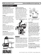
Both a check valve and a shut-off valve
are recommended for each pump. The
check valve is used to prevent backflow
into the sump. The shut-off valve is
used to manually stop system flow
during pump servicing.
Electrical Connections
The power cable mounted to the pump
must not be modified in any way. This
pump is provided with a 3 wire cord and
3 prong grounded plug that must be
connected into a 3 wire grounded Ground
Fault receptacle. Do not bypass grounding
wires or remove ground prongs from plug.
This pump requires separate, properly
fused and grounded branch circuit. Use of
a ground fault circuit interrupter (GFCI) is
strongly recommended.
The electrical outlet or panel shall be
within the length limitations of the pump
power cord, and at least 4 feet above floor
level to minimize possible hazards from
flood conditions. Do Not use an extension
cord.
IF USED with Control Panel -
Any splice
between the pump and the control panel
must be made in accordance with the
electric codes. It is recommended that a
junction box, if used, be mounted outside
the sump or be of at a minimum Nema
4 construction if located within the wet
well.
DO NOT USE THE POWER CABLE TO
LIFT PUMP.
Always rely upon a Certified
Electrician for installation.
Overload Protection:
Single Phase
- The stator in-winding
overload protector used is referred to
as an inherent overheating protector
and operates on the combined effect
of temperature and current. This means
that the overload protector will trip out
and shut the pump off if the windings
become too hot, or the load current
passing through them becomes too high.
IMPORTANT ! -
The overload will then
automatically reset and start the pump
up after the motor cools to a safe
temperature. In the event of an overload,
the source of this condition should be
determined and corrected immediately.
WARNING! - DO NOT LET
THE PUMP CYCLE OR RUN IF
AN OVERLOAD CONDITION
OCCURS !
If current through the temperature
sensor exceeds the values listed, an
intermediate control circuit relay must be
used to reduce the current or the sensor
will not work properly.
TEMPERATURE SENSOR ELECTRICAL
RATINGS
Volts
Continuous
Amperes
Inrush
Amperes
110-120
3.00
30.0
220-240
1.50
15.0
Wire Size:
If longer power cable is required consult a
qualified electrician for proper wire size.
Pre-Operation
1. Check Voltage and Phase Compare
the voltage and phase information
stamped on the pump name plate.
2.
Check Pump Rotation
- Improper
motor rotation can result in poor
pump performance and can damage
the motor and/or pump. Incorrect
rotation for Single-Phase pumps is
unlikely. If the rotation is incorrect
contact factory.
3.
Name Plate
- Record the information
from the pump name plate to
drawing in front of manual for future
reference.
4.
Insulation Test
- An insulation
(megger) test should be performed
on the motor. Before the pump is put
into service. The resistance values
(ohms) as well as the voltage (volts)
and current (amps) should be
recorded.
5.
Pump-Down Test
- Be sure pump
has been properly wired, lowered into
the basin, sump or lift station, check
the system by filling with liquid and
allowing the pump to operate through
its pumping cycle. The time needed to
empty the system, or pump-down
time along with the volume of water,
should be recorded.
Maintenance
No lubrication or maintenance is required.
Perform the following checks when pump
is removed from operation or when pump
performance deteriorates:
a). Inspect motor chamber for oil level
and contamination.
b). Inspect impeller and body for
excessive build-up or clogging.
c). Inspect motor and bearings.
d). Inspect seal for wear or leakage.
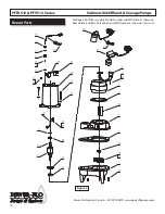
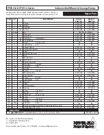
Servicing
NOTE: Item numbers in ( ) refer to Figure 4
Cooling Oil -
Anytime the pump is
removed from operation, the cooling oil
in the motor housing should be checked
visually for oil level and contamination.
To check oil, set unit upright. Remove
pipe plug from housing. With a flashlight,
visually inspect the oil in the housing
to make sure it is clean and clear, light
amber in color and free from suspended
particles. Milky white oil indicates the
presence of water. Oil level should be just
above the motor when pump is in vertical
position.
Installation & Service
PFEV512 & PFV512 Series
Submersible Effluent & Sewage Pumps


