background image

9

OPERATION

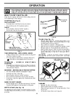
OIL 

LEVEL

FIG. 12

BEFORE START ING ENGINE

IMPORTANT

:  BE VERY CAREFUL NOT TO ALLOW DIRT 

TO ENTER THE ENGINE WHEN CHECKING OR ADDING 

OIL OR FUEL.  USE CLEAN OIL AND FUEL AND STORE IN 

APPROVED, CLEAN, COVERED CONTAINERS.  USE CLEAN 

FILL FUNNELS.

CHECK ENGINE OIL LEVEL (See Fig. 12)

• 

The engine in your unit has been shipped, from the 

factory, already filled with SAE 30 summer weight oil.

• 

With engine level, clean area around oil filler plug and 

remove plug.

• 

Engine oil should be to point of overflowing when engine 

is level.  For ap proxi mate capacity see “PROD UCT 

SPEC I FI CA TIONS” on page 3 of this manual.  All oil 

must meet A.P.I. Service  Classification SF-SJ.

•  Reinstall engine oil cap and tighten.
•  For cold weather operation you should change oil for 

easier starting (See oil viscosity chart  in the Mainte-

nance sec tion of this manual).

•  To change engine oil, see the Maintenance section in 

this manual.

ADD GASOLINE 

•  Fill fuel tank to bottom of filler neck. Do not overfill.  

Use fresh, clean, regular un lead ed gasoline with a 

minimum of 87 octane.  (Use of  leaded gasoline will 

increase carbon and lead oxide deposits and reduce 

valve life).  Do not mix oil with gasoline.  Purchase fuel 

in quan ti ties that can be used within 30 days to assure 

fuel freshness.

CAUTION:  Fill to within 1/2 inch of top 

of fuel tank to prevent spills and to allow 

for fuel expansion.  If gasoline is ac-

 ci den tal ly spilled, move machine away 

from area of spill.  Avoid creating any 

source of ignition until gasoline vapors 

have disappeared.  
Wipe off any spilled oil or fuel.  Do not 

store, spill or use gasoline near an 

open flame.

IMPORTANT:

  WHEN OPERATING IN TEMPERATURES 

BELOW32°F(0°C), USE FRESH, CLEAN WINTER GRADE 

GAS O LINE TO HELP INSURE GOOD COLD WEATHER 

START ING.

CAUTION:  Alcohol blended fuels (called 

gas o hol or using ethanol or methanol) can at-

tract moisture which leads to sep a ra tion and 

for ma tion of acids during storage.  Acidic gas 

can damage the fuel system of an engine while 

in storage.  To avoid engine problems, the fuel 

system should be emptied before stor age of 

30 days or longer.  Drain the gas tank, start 

the engine and let it run until the fuel lines 

and carburetor are empty.  Use fresh fuel next 

sea son.  See Storage In struc tions for additional 

information.  Never use engine or carburetor 

cleaner products in the fuel tank or permanent 

damage may occur.

•  Swing the handle in the opposite direction you wish 

to turn, being careful to keep feet and legs away from 

tines.

•  When you have completed your turn-around, release 

the drive control bar and lower handle.  Place shift  

lever in till position and move throttle control to de sired 

speed.  To begin tilling, hold drive control bar against 

the handle.

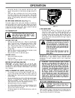
OUTER SIDE SHIELDS (See Fig. 11)

The back edges of the outer side shields are slotted so 

that the shields can be raised for deep tilling and low ered 

for shal low tilling to protect small plants from being buried.  

Loosen nut “A” in slot and nut “B”.  Move shield to desired 

position (both sides).  Retighten nuts.

TO TRANSPORT

CAUTION:  Before lifting or trans port ing, 

allow tiller engine and muffler to cool.  

Disconnect spark plug wire.  Drain 

gasoline from fuel tank.

AROUND THE YARD

•  Release the depth stake pin.  Move the depth stake 

down  to the top hole  for transporting the tiller.  Place 

depth stake pin in hole of depth stake to lock in posi-

tion.  This prevents tines from scuffing the ground.

•  Place shift lever indicator in “F” (forward) position for 

transporting.

•  Hold the drive control bar against the handle to start 

tiller movement.  Tines will not turn.

•  Move throttle control to desired speed.

AROUND TOWN

•  Disconnect spark plug wire.
•  Drain fuel tank.
•  Transport in upright position to prevent oil leakage.

TO START ENGINE (See Fig. 13)

CAUTION:  Keep drive control bar in 

“DISENGAGED” position when start-

 ing en gine.

When starting engine for the first time or if engine has run 

out  of fuel, it will take extra pulls of the recoil starter to 

move fuel from the tank to the engine.

Summary of Contents for 418121

Page 1: ...AR EYE PROTECTION DURING OPERATION Visit our website www poulan pro com WARNING Read this Manual and follow all Warnings and Safety Instructions Failure to do so can result in serious injury IMPORTANT MANUAL Do Not Throw Away 418121 12 10 07 TH Printed in U S A ...

Page 2: ...stop the unit and disengage the controls quickly Never allow children to operate the equipment Never allow adults to operate the equipment without proper instruction Keep the area of operation clear of all persons par ticularly small children and pets PREPARATION Thoroughly inspect the area where the equipment is to be used and remove all foreign objects Disengage all clutches and shift into neutr...

Page 3: ...bustion engine and should not be used on or near any unimprovedforest covered brush coveredorgrasscovered land unless the engine s exhaust system is equipped with a spark arrester meeting applicable local laws if any If a spark arrester is used it should be maintained in effective working order by the operator In the state of California a spark arrester is required by law Section 4442 of the Calif...

Page 4: ... been assembled at the factory with exception of those parts left unassembled for shipping purposes To ensure safe and proper operation of your tiller all parts and hardware you assemble must be tightened securely Use the correct tools as necessary to insure proper tightness FRONT OPERATOR S POSITION LEFT RIGHT FIG 1 1 Hairpin Clip 1 Carriage Bolt 3 8 16 UNC x 1 Grade 5 1 Center Locknut 3 8 16 UNC...

Page 5: ...y is lowered into position HANDLE ASSEMBLY FIG 3 HANDLE ASSEMBLY GEARCASE NOTCH HANDLE LOCK VIEWED FROM R H SIDE OF TILLER LOOSEN HANDLE LOCK LEVER TO MOVE TIGHTEN HANDLE LOCK LEVER TO HOLD handles_34 CARRIAGE BOLT SLOT GEARCASE HANDLE LOCK FLAT WASHER HANDLE LOCK LEVER PIVOT BOLT LOCKNUT HANDLE BASE FIG 5 Rotate handle assembly down Insert rear carriage bolt first with bolt head on L H side of ti...

Page 6: ...clip through hole of shift rod to secure FIG 7 FIG 6 END OF CLUTCH CABLE CONTROL BAR CONTROL BAR BRACKET CONTROL BAR BRACKET CLUTCH CABLE ATTACH CLUTCH CABLE See Fig 6 Hook end of clutch cable through hole in control bar bracket CHECK TIRE PRESSURE The tires on your unit were overinflated at the factory for shipping purposes Correct and equal tire pressure is important for best tilling performance...

Page 7: ...ds of the American National Standards Institute CHOKE CONTROL Used when starting a cold engine DEPTH STAKE Controls depth at which tiller will dig DRIVE CONTROL BAR Used to engage tines LEVELING SHIELD Levels tilled soil OUTER SIDE SHIELD Adjustable to protect small plants from being buried RECOIL STARTER HANDLE Used to start the engine SHIFT LEVER Used to shift transmission gears SHIFT LEVER INDI...

Page 8: ...leaseorrocktiller forward and backward until are able to shift gears DEPTH STAKE See Fig 10 The depth stake can be raised or lowered to allow you more versatile tilling and cultivating or to more easily transport your tiller FIG 9 pth_stake_2 TILLING See Fig 11 Release depth stake pin Pull the depth stake up for increased tilling depth Place depth stake pin in hole of depth stake to lock in positi...

Page 9: ...ids during storage Acidic gas can damage the fuel system of an engine while in storage To avoid engine problems the fuel system should be emptied before storage of 30 days or longer Drain the gas tank start the engine and let it run until the fuel lines and carburetor are empty Use fresh fuel next season SeeStorageInstructionsforadditional information Never use engine or carburetor cleaner product...

Page 10: ...eason to further condition the soil You will find tilling much easier if you leave a row un tilled between passes Then go back between tilled rows See Fig 14 There are two reasons for doing this First wide turns are much easier to negotiate than about faces Second the tiller won t be pulling itself and you toward the row next to it TINE SHEAR PINS The tine assemblies on your tiller are secured to ...

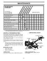
Page 11: ...ine operation Check for loose fasteners LUBRICATION Keep unit well lubricated See LUBRICATION CHART LUBRICATION CHART MAINTENANCE SCHEDULE FILL IN DATES AS YOU COMPLETE REGULAR SERVICE Check Engine Oil Level Change Engine Oil Oil Pivot Points Inspect Air Screen Inspect Spark Arrester Muffler Clean or Replace Air Cleaner Cartridge Clean Engine Cylinder Fins Replace Spark Plug B E F O R E E A C H U ...

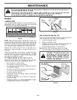
Page 12: ...rature NOTE Although multi viscosity oils 5W 30 10W 30 etc improve starting in cold weather these multi viscosity oils will result in increased oil consumption when used above 40 F 4 C Check your engine oil level more frequently to avoid possible engine damage from running low on oil Change the oil after every 25 hours of operation or at least once a year if the tiller is not used for 25 hours in ...

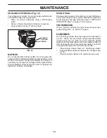
Page 13: ... 1 oz of EP 1 Grease CLEANING Do not clean your tiller when the engine and transmission are hot We do not recommend using pressurized water garden hose etc to clean your unit unless the gasket area around the transmission and the engine muffler air filter and carburetor are covered to keep water out Water in engine will shorten the useful life of your tiller Clean engine wheels finish etc of all f...

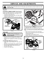
Page 14: ...amage rubber TO REMOVE WHEEL See Fig 21 Place blocks under transmission to keep tiller from tipping Remove outer side shield by removing nuts A and B Removeinnersideshieldbyremovingnuts C and D Remove hairpin clip and clevis pin from wheel Remove wheel and tire Repair tire and reassemble tire_4 CLEVIS PIN INNER SIDE SHIELD OUTER SIDE SHIELD NUT D HAIRPIN CLIP NUT C NUT A NUT B FIG 21 HANDLE LOW PO...

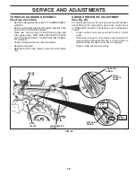
Page 15: ...N GROOVE ON TOP OF IDLER PULLEY NOTE POSITION OF BELT TO GUIDES Check belt adjustment as described below Replace belt guard Reposition wheel and replace clevis pin and hairpin clip GROUND DRIVE BELT ADJUSTMENT See Fig 23 For proper belt tension the extension spring should have about 5 8 inch 16 mm stretch when drive control bar is in ENGAGED position This tension can be attained as follows Loosen ...

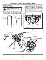
Page 16: ...To maintain the superb tilling performance of this machine the tines should be checked for sharpness wear and bending particularly the tines which are next to the transmission If the gap between the tines exceeds 3 1 2 inches 9 cm they should be replaced or straightened as necessary New tines should be assembled as shown in Fig 26 Sharpened tine edges will rotate rearward from above tine_3 TINE TI...

Page 17: ...throttle lever up until it touches high speed stop and hold in this position Tighten cable clamp screw securely TO ADJUST CARBURETOR Thecarburetorhasbeenpresetatthefactoryandadjustment should not be necessary However engine performance can be affected by differences in fuel temperature altitude or load If the carburetor does need adjustment contact your nearest authorized service center department...

Page 18: ...replace belts if necessary See belt re placement instructions in the Service and Adjustments section of this manual Lubricate as shown in the Maintenance section of this manual Be sure that all nuts bolts and screws are securely fastened Inspect moving parts for damage breakage and wear Replace if necessary Touch up all rusted or chipped paint surfaces sand lightly before painting ENGINE FUEL SYST...

Page 19: ...nd clean carburetor 6 Stale or dirty fuel 6 Empty fuel tank and refill with fresh gasoline 7 Water in fuel 7 Empty fuel tank and carburetor and refill tank with fresh gasoline 8 Clogged fuel tank 8 Remove fuel tank and clean 9 Spark plug wire loose 9 Connect and tighten spark plug wire 10 Dirty engine air screen 10 Clean engine air screen 11 Dirty clogged muffler 11 Clean replace muffler 12 Carbur...

Page 20: ...20 SERVICE NOTES ...
Page 21: ...nstructions furnished This Warranty does not apply to any product which has been subjected to alteration misuse abuse improper assembly or installation delivery damage or to normal wear of the product 5 Exclusions Excluded from this Warranty are belts tines tine adapters normal wear normal adjustments stan dard hardware and normal maintenance 6 In the event you have a claim under this Warranty you...

Page 22: ... b Description of part For Technical Assistance call 1 800 829 5886 For a Parts Manual go to our website www poulan pro com support asp NOTE PoulanProprovidespartsandservicethroughitsauthorizeddistributorsanddealers therefore all requests for parts and service should be directed to your local dealer s The philosophy of Electrolux Home Products is to continually improve all of its products If the o...

Reviews: