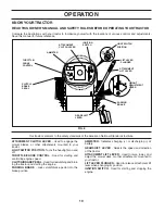
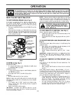
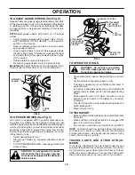
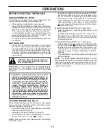
background image

19

SERVICE AND ADJUSTMENTS

WARNING: TO  AVOID  SE RI OUS IN 

JU RY, BEFORE PERFORMING ANY SERVICE OR ADJUST-

MENTS:


Depress clutch/brake pedal fully and set parking brake.


Place gearshift lever in neutral (N) position.


Place attachment clutch  in “DISENGAGED” position.


Turn ignition key to  “STOP” and remove key.


Make sure the blades and all moving parts have completely stopped.


Disconnect spark plug wire from spark plug and place wire where it cannot come in contact  

 with 

plug.

TRACTOR

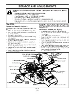
TO REMOVE MOWER (See Fig. 17)

Mower will be easier to remove from the right side of trac-
tor.
•      Place attachment clutch in “DIS EN GAGED” position.
•     Move attachment lift lever forward to low er mower to 

its lowest po si tion.

•      Roll belt off engine pulley.
•         Remove small retainer spring, and remove clutch spring 

off pulley bolt.

•      Remove large retainer spring, slide col lar off and push 

housing guide out of brack et.

•      Disconnect anti-swaybar from chas sis bracket by re-

mov ing re tain er spring.

•      Disconnect suspension arms from rear deck brackets 

by removing retainer springs.

•      Disconnect front links from deck by re mov ing retainer 

springs.

•      Raise lift lever to raise suspension arms. Slide mower 

out from under tractor.

IMPORTANT:

 IF AN ATTACHMENT OTHER THAN THE MOWER 

DECK IS TO BE MOUNTED ON THE TRAC TOR, REMOVE THE 
FRONT LINKS AND HOOK THE CLUTCH SPRING INTO SQUARE 
HOLE IN FRAME.

TO INSTALL MOWER (See Fig. 17)

•      Raise attachment lift lever to its high est position.
•      Slide mower under tractor with defl ector shield to right 

side of tractor.

•      Lower lift lever to its lowest po si tion.
•     Connect front links to mower deck and secure with 

retainer springs..

•     Connect suspension arms to rear deck brackets and 

secure with retainer springs.

•     Connect anti-swaybar to chassis bracket and secure 

with retainer spring.

•         Push clutch cable housing guide into bracket, slide col-

lar onto guide and secure with large retainer spring.

•      Place fl at washer and clutch spring on idler pulley bolt 

and secure with small retainer spring.

•      Install belt onto engine pulley.

SUSPENSION
ARMS

RETAINER SPRINGS
(BOTH SIDES)

RETAINER SPRING

ANTI-SWAY BAR

HOUSING GUIDE

FRONT LINK

COLLAR

ENGINE PULLEY

LARGE 
RETAINER 
SPRING

CLUTCH SPRING

SMALL RETAINER SPRING

BRACKET

SQUARE HOLE

FIG. 17

DEFLECTOR SHIELD

SMALL RETAINER SPRING

CLUTCH SPRING

FLAT WASHER

Summary of Contents for 191920

Page 1: ...OR ALWAYS WEAR EYE PROTECTION DURING OPERATION WARNING ReadthisOwner sManualandfollowallWarn ings and Safety Instructions Failure to do so can result in serious injury IMPORTANT MANUAL Do Not Throw Away 191920 03 02 04 RD Printed in U S A 02478 ...

Page 2: ...he manual and on the machine before starting Only allow responsible adults who are familiar with the instructions to operate the machine Clear the area of objects such as rocks toys wire etc which could be picked up and thrown by the blade Be sure the area is clear of other people before mow ing Stop machine if anyone enters the area Never carry passengers Do not mow in reverse unless absolutely n...

Page 3: ...the watchful care of another responsible adult Be alert and turn machine off if children enter the area Before and when backing look behind and down for small children Mow up and down slopes 15 Max not across Remove obstacles such as rocks tree limbs etc Watchforholes ruts orbumps Uneventerraincouldoverturn the machine Tall grass can hide obstacles Use slow speed Choose a low gear so that you will...

Page 4: ...using your tractor Follow the instructions under Maintenance and Stor age sections of this owner s manual WARNING This tractor is equipped with an internal com bustion engine and should not be used on or near any unimprovedforest covered brush coveredorgrass covered land unless the engine s exhaust system is equipped with a spark arrester meeting applicable local or state laws if any If a spark ar...

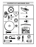
Page 5: ...Shaft Steering Wheel Adapter Seat 2 Keys Slope Sheet Key 1 Hex Bolt 1 4 28 x 1 1 4 1 Locknut 1 4 28 1 Locknut 1 2 20 1 Oil Drain Tube 1 Knob 1 Washer 17 32 x 1 3 16 x 12 Gauge 4 Washers 3 8 x 3 4 x 14 Ga 4 Wheels 4 Adjusting Bar 4 Retainer Springs double loop 4 Clevis Pins 4 Locknut 3 8 16 4 Shoulder Bolt Gauge Wheels ...

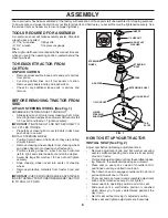
Page 6: ...RELY TO 10 12 FT LBS TORQUE Place tabs of steering boot over tab slots in dash and push down to secure INSTALL STEERING WHEEL Position front wheels of the tractor so they are pointing straight forward Remove steering wheel adapter from steering wheel and slide adapter onto steering shaft extension Position steering wheel so cross bars are horizontal left to right and slide inside boot and onto ada...

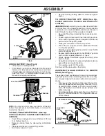
Page 7: ... of other people and objects Be sure all the above assembly steps have been com pleted Check engine oil level and fill fuel tank with gasoline Sit on seat in operating position depress clutch brake pedal and set the parking brake Place gear shift lever in neutral N position Press lift lever plunger and raise attachment lift lever to its highest position Starttheengine Afterenginehasstarted movethr...

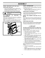
Page 8: ... at the factory for shipping purposes Correct tire pressure is important for best cutting performance Reduce tire pressure to PSI shown in PRODUCT SPECIFICATIONS section of this manual CHECK DECK LEVELNESS For best cutting results mower housing should be properly leveled See TOLEVELMOWERHOUSING intheService and Adjustments section of this manual CHECK FOR PROPER POSITION OF ALL BELTS See the figur...

Page 9: ...ould result in serious injury or death The safety alert symbol is used to identify safety inform ation about hazards which can result in death serious injury and or property damage DANGER indicates a hazard which if not avoided will result in death or serious injury WARNING indicates a hazard which if not avoided could result in death or serious injury CAUTION indicates a hazard which if not avoid...

Page 10: ... starting the engine PARKING BRAKE Locks clutch brake pedal into the brake position AMMETER Indicates charging or discharging of battery GEARSHIFT LEVER Selects the speed and direction of the tractor ATTACHMENT LIFT LEVER Used to raise lower and adjust the mower deck or other attachments mounted to your tractor LIFT LEVER PLUNGER Used to release attachment lift lever when changing its position IGN...

Page 11: ...ition key to OFF position and remove key Always remove key when leaving tractor to prevent unauthorized use Never use choke to stop engine IMPORTANT LEAVING THE IGNITION SWITCH IN ANY POSITION OTHER THAN OFF WILL CAUSE THE BATTERY TO BE DISCHARGED DEAD ATTACHMENT CLUTCH LEVER ENGAGED POSITION IGNITION KEY DISENGAGED POSITION PARKING BRAKE ENGAGED POSITION GEAR SHIFT LEVER THROTTLE CHOKE CONTROL LE...

Page 12: ...h the ground and cause you to lose control of your tractor TO OPERATE MOWER See Fig 9 Your tractor is equipped with an operator presence sens ing switch Any attempt by the operator to leave the seat with the engine running and the attachment clutch engaged will shut off the engine You must remain fully and centrally positioned in the seat to prevent the engine from hesitat ing or cutting off when ...

Page 13: ...ENGINE CHECK ENGINE OIL LEVEL The engine in your tractor has been shipped from the factory already filled with summer weight oil Check engine oil with tractor on level ground Remove oil fill cap dipstick and wipe clean reinsert the dipstick and screw cap tight wait for a few seconds remove and read oil level If necessary add oil until FULL mark on dipstick is reached Do not overfill For cold weath...

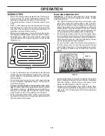
Page 14: ...speed that will suit the terrain and give best performance of the attachment being used MULCHING MOWING TIPS IMPORTANT FOR BEST PERFORMANCE KEEP MOWER HOUSING FREE OF BUILT UP GRASS AND TRASH CLEAN AFTER EACH USE The special mulching blade will recut the grass clip pings many times and reduce them in size so that as they fall onto the lawn they will disperse into the grass and not be noticed Also ...

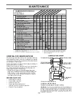
Page 15: ...RT dSPINDLE ZERK dFRONT WHEEL BEARING ZERK cSAE 30 OR 10W30 MOTOR OIL dGENERAL PURPOSE GREASE eREFER TO MAINTENANCE ENGINE SECTION IMPORTANT DO NOT OIL OR GREASE THE PIVOT POINTS WHICH HAVE SPECIAL NYLON BEARINGS VISCOUS LUBRICANTS WILL ATTRACT DUST AND DIRT THAT WILL SHORTEN THE LIFE OF THE SELF LUBRICATING BEARINGS IF YOU FEEL THEY MUST BE LUBRICATED USE ONLY A DRY POWDERED GRAPHITE TYPE LUBRICA...

Page 16: ...rator to leave the seat without first setting the parking brake should shut off the engine When the engine is running and the attachment clutch is engaged any attempt by the operator to leave the seat should shut off the engine The attachment clutch should never operate unless the operator is in the seat BLADE CARE Forbestresultsmowerbladesmustbekeptsharp Replace bent or damaged blades 5 8 BOLT OR...

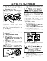
Page 17: ... is tightened securely for accurate reading Keep oil at FULL line on dipstick YELLOW CAP ENGINE LUBRICATION Only use high quality detergent oil rated with API service classification SF SJ Select the oil s SAE viscosity grade according to your expected operating temperature TEMPERATURE RANGE ANTICIPATED BEFORE NEXT OIL CHANGE SAE VISCOSITY GRADES 20 0 30 40 80 100 30 20 0 20 30 40 F C 32 10 10 60 5...

Page 18: ... the useful life of your tractor Use compressed air or a leaf blower to remove grass leaves and trash from tractor and mower IN LINE FUEL FILTER See Fig 16 The fuel filter should be replaced once each season If fuel filter becomes clogged obstructing fuel flow to carburetor replacement is required With engine cool remove filter and plug fuel line sec tions Place new fuel filter in position in fuel...

Page 19: ...gs Disconnect front links from deck by removing retainer springs Raise lift lever to raise suspension arms Slide mower out from under tractor IMPORTANT IFANATTACHMENTOTHERTHANTHEMOWER DECK IS TO BE MOUNTED ON THE TRACTOR REMOVE THE FRONTLINKSANDHOOKTHECLUTCHSPRINGINTOSQUARE HOLE IN FRAME TO INSTALL MOWER See Fig 17 Raise attachment lift lever to its highest position Slide mower under tractor with ...

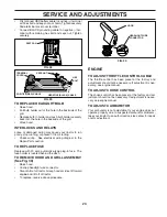
Page 20: ... equal number of turns FIG 21 BOTH FRONT LINKS MUST BE EQUAL IN LENGTH FIG 20 TO LEVEL MOWER HOUSING Adjust the mower while tractor is parked on level ground or driveway Make sure tires are properly inflated See PRODUCT SPECIFICATIONS section of this manual If tires are over or underinflated you will not properly adjust your mower SIDE TO SIDE ADJUSTMENT See Figs 18 and 19 Raise mower to its highe...

Page 21: ...an five 5 feet to stop at highest speed in highest gear on a level dry concrete or paved surface then brake must be checked and adjusted TO CHECK BRAKE Park tractor on a level dry concrete or paved surface depress clutch brake pedal all the way down and en gage parking brake Place gear shift lever in neutral N position Therearwheelsmustlockandskidwhenyoutrytomanually push the tractor forward If th...

Page 22: ... START ENGINE WITH A WEAK BATTERY See Fig 27 WARNING Lead acid batteries gen erate explosive gases Keep sparks flameandsmokingmaterialsawayfrom batteries Always wear eye protection when around batteries If your battery is too weak to start the engine it should be recharged See BATTERY in the Maintenance section of this manual If jumper cables are used for emergency starting follow this procedure I...

Page 23: ...ift off of tractor To replace reverse above procedure FIG 28 FIG 29 SEAT PAN KEPS NUT HEX BOLT POSITIVE RED CABLE NEGATIVE BLACK CABLE TERMINAL COVER First connect RED battery cable to positive terminal with hex bolt and keps nut as shown Tighten securely Slide terminal cover over terminal Connect BLACK grounding cable to negative ter minal with remaining hex bolt and keps nut Tighten securely ENG...

Page 24: ...FUEL SYSTEM PARTS SUCH AS CARBURETOR FUEL FILTER FUEL HOSE OR TANK DURING STORAGE ALSO EXPERIENCE INDICATES THAT ALCOHOL BLENDED FUELS CALLED GASOHOL OR USING ETHANOLORMETHANOL CANATTRACTMOISTUREWHICH LEADSTOSEPARATIONANDFORMATIONOFACIDSDURING STORAGE ACIDIC GAS CAN DAMAGE THE FUEL SYSTEM OF AN ENGINE WHILE IN STORAGE Empty the fuel tank by starting the engine and let it run until the fuel lines a...

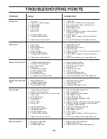
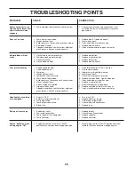
Page 25: ...Faulty ignition switch 7 Check replace ignition switch 8 Faulty solenoid or starter 8 Check replace solenoid or starter 9 Faulty operator presence switch es 9 Contact an authorized service center department Engine clicks but will not 1 Weak or dead battery 1 Recharge or replace battery start 2 Corroded battery terminals 2 Clean battery terminals 3 Loose or damaged wiring 3 Check all wiring 4 Fault...

Page 26: ... Mower deck not level 4 Level mower deck 5 Low uneven tire air pressure 5 Check tires for proper air pressure 6 Worn bent or loose blade 6 Replace sharpen blade Tighten blade bolt 7 Buildup of grass leaves and trash under mower 7 Clean underside of mower housing 8 Mower drive belt worn 8 Replace mower drive belt 9 Blades improperly installed 9 Reinstall blades sharp edge down 10 Improper blades us...

Page 27: ...sed for rental or commercial purposes is limited to 90 days from the date of original purchase 5 This Warranty applies only to products which have been properly assembled adjusted operated and maintained in accor dance with the instructions furnished This Warranty does not apply to any product which has been subjected to alteration misuse abuse improper assembly or installation delivery damage or ...

Page 28: ...of the Power Train Component and parts The cost of normal maintenance and replacement of service items which are not defective shall be paid for by the original purchaser C Securing Warranty Service Warranty service can be arranged for by contacting either a Tecumseh Authorized Service Outlet anyTecumseh Registered Service Dealer Tecumseh Authorized Service Distributor or Tecumseh Central Warehous...

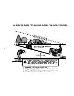
Page 29: ...the face Do not mow slopes greater than 15 degrees Make turns gradually to prevent tipping or loss of control Exercise extreme caution when changing direction on slopes 1 Fold this page along dotted line indicated above 2 Hold page before you so that its left edge is vertically parallel to a tree trunk or other upright structure 3 Sight across the fold in the direction of hill slope you want to me...

Page 30: ...rimmers Brushcutters and Blowers 3 For replacement parts have available the following information a Model Number Manufacturer s I D Number b Description of part NOTE Electrolux Home Products provides parts and service through its authorized distributors and dealers therefore all requests for parts and service should be directed to your local dealer s The philosophy of Electrolux Home Products is t...

Reviews: