background image

Part No. 27/20334

Component Replacement 39

Component Replacement - Page 39

6.21

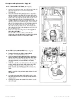
Automatic Air Vent 

(See Fig. 30)

a.  Remove the white front case, base panel and white left

hand side panel. See 5.1, 5.2 & 5.3 in 'Routine
Maintenance'.

b.

Close the central heating isolating valves, reduce the
system pressure by opening the pressure relief valve,
then part drain the water from the boiler by opening the
bleed valve on the right hand side of the diverter valve.

c.

Using a spanner to prevent the retaining nut from
rotating unscrew the auto air vent and remove from the
appliance. If there is insufficient space, removal will be
eased if the complete auto air vent and pipe assembly
is disconnected from the heat exchanger and then
raised above the top of the air box. To do this the fan
and fluehood will need to be removed, see 5.4 & 5.5 in
‘Routine Maintenance’

d.  Fit new air vent and sealing washer 

ensuring the air

vent cap is left loose.

Re-assemble in reverse order, ensure that the
grommet is correctly positioned. Re-charge the system
as described in section 1.6 and check for leaks.

6.22

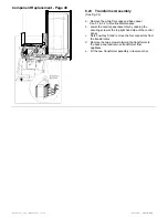
Pressure Relief Valve

 (See Fig. 31)

a.

Remove the white front case and base panel.

See 5.1 & 5.2 in ’Routine Maintenance’.

b.

Close the central heating isolating valves, reduce the
system pressure by opening the pressure relief valve,
then drain the water from the appliance by removing
the drain off screw on the underside of the pump
manifold.

c.

Undo the outlet tube nut and fully remove the two grub
screws holding the pressure relief valve to the pump
manifold, undo the top compression joint on the
pressure relief valve discharge pipe then remove the
valve.

Note:

 The outlet of the pressure relief valve is an olive

connection.

d.

Fit the new pressure relief valve using a new ‘O’ ring
seal and soap solution as a lubricant. Re-assemble in
reverse order.

e.

Recharge the system as described in section 1.6 and
check for leaks.

Summary of Contents for Puma Flowsure+

Page 1: ...ces are installed by competent persons in accordance with the above regulations Failure to install appliances correctly could lead to prosecution The polythene bags used for packaging are a potential hazard to babies and young children and MUST BE DISPOSED OF IMMEDIATELY LEAVE THESE INSTRUCTIONS WITH THE USER FOR USE ON FUTURE CALLS For Use With Natural Gas G20 Only At 20mbar For Use in GB IE IMPO...

Page 2: ...ing Over to the User 25 4 Servicing 26 5 Routine Maintenance 27 5 1 Remove the White Front Case 27 5 2 Remove Base Panel 27 5 3 Remove the Air Box Covers 27 5 4 Remove the Fan Assembly 27 5 5 Remove the Flue Hood 27 5 6 Remove the Combust Cham Front Panel 27 5 7 To Inspect and Clean the Boiler 27 5 8 To Remove the Burner 29 5 9 Gas Pressure Adjustment 29 5 10 The Central Heating Sealed System 29 5...

Page 3: ...xternal 3A Packed Weight 58 5kg 129lbs Water Content 1 85 litres C H Connections Gas Gas B S P F Gas Cock Connections Water Inlet DHW 15mm Compression Isolating Valve Outlet DHW 15mm Copper Pipe Flow CH 22mm Compression Isolating Valve Return CH 22mm Compression Isolating Valve Safety Discharge 15mm Copper Pipe C H Sealed System Operating Pressure 2 5bar 36 3lb in Max Operating Pressure 0 5bar 7 2...

Page 4: ...oilers are designed for use with fully pumped sealed system only They are supplied fully tested and assembled with a circulating pump diverter valve pressure gauge pressure relief valve and expansion vessels Fig 1 shows the main components of the boiler assembly A central heating switch controls the choice of service between central heating hot water and hot water only The boiler water flow system...

Page 5: ...Part No 27 20334 Introduction 5 Introduction Page 5 ...

Page 6: ...ly of gas An existing service pipe must NOT be used without prior consultation with the Local Gas Region A gas meter can only be connected by the Local Gas Region or by a Local Gas Region Contractor An existing meter should be checked preferably by the Gas Region to ensure the meter is adequate to deal with the rate of gas supply required Installation pipes should be fitted in accordance with BS 6...

Page 7: ...ide for Gas Installations in Timber Frame Housing Reference DM2 If in doubt advice must be sought from the Local Gas Region of British Gas The combination boiler may be installed in any room or internal space although particular attention is drawn to the requirements of the current I E E Wiring Regulations and in Scotland the electrical provisions of the Building Regulations applicable in Scotland...

Page 8: ... also available for flue heights up to 8025 mm Part No 31 19037 when used in conjunction with one metre twin tube extension kits Part No 31 19038 A Pitched Roof Flashing kit Part No 31 19041 and Flat Roof Flashing kit Part No 31 19040 are available for use with the vertical flue systems 135 Off set kits are available for both types Part No 31 19035 concentric and Part No 31 19039 twin tube The sit...

Page 9: ...g surface should be lagged to prevent heat loss and any possible freezing particularly where pipes run through roof spaces and ventilated under floor spaces If the capacity of the central heating system should exceed 100 litres an additional vessel should be installed on the return to the combination boiler from the heating system Fig 4 Guidance on vessel sizing is given in Table 3 To allow the ma...

Page 10: ...tomatic pressure reducing valve or flow restrictor The pressure booster pump must be capable of pressurising the system to a minimum of 1 0 bar 14 p s i measured at the appliance The cistern should be supplied through a temporary connection from a service pipe or cold water distributing pipe The unit may remain permanently connected to the heating system to provide limited water make up Provisions...

Page 11: ...e central heating output to match your heating system requirement Systems which have very low water content and a low heating requirement may benefit by reducing the maximum boiler output This is achieved by rotation of the range rate adjuster located on the electronic modulation control board see Fig 26 The boiler central heating output can be adjusted between the maximum and minimum values state...

Page 12: ...e fitted between the expansion vessel and the storage cylinder DHW Store Temperature Water is stored in the tank at approximately 73 C To ensure a safe delivery temperature a thermostatic mixing valve is fitted in the hot water outlet and should be adjusted to produce a hot water delivery temperature of 60 C ...

Page 13: ...he mains electricity supply must provide means of completely isolating the electrical supply to the combination boiler and its ancillary controls The appliance is designed to be the wiring centre for the installation therefore no additional live supplies are required from either timers or room thermostats Isolation is preferably by the use of a fused three pin plug and unswitched shuttered socket ...

Page 14: ... incorporated into template Top Clearance The top clearance should be a minimum of 160mm but 300mm is preferred to allow removal of the central heating expansion vessel without removing the appliance from the wall if replacement is required Bottom Clearance A bottom clearance of 220mm is required between the appliance and any surface Frontal Clearance A minimum of 500mm is required in front of the...

Page 15: ...approx 50mm and lift off the supporting top hooks See Fig 13 b Remove the base cover by removing the two fixing screws and push the cover towards the rear to release c Each side panel can now be individually removed by removing the two front fixing screws loosening the lower rear fixing screw and sliding the panel upwards to unhook from the upper rear fixing Place each panel and screws safely to o...

Page 16: ...l panel or other unsubstantial structure as this may result in damage to the appliance DO NOT pivot the appliance onto its base as damage may occur to the underside n Align the boiler with the bottom fixing hole and secure using a screw from the Fittings Card 2 3 Installation Storage Tank a Connect the water controls inlet assembly to the base of the tank See Fig 15 b Connect the domestic service ...

Page 17: ... pipe assembly to the pump inlet manifold Use a new fibre washer from the fittings card l Take the side casing bracket assembly from the storage kit and fit the thermostat using the two M4 screws provided in the Fittings Pack Secure the bracket assembly in place using the two self tapping screws from the boiler side panel for the upright portion Remove the two M5 screws from the Fittings Pack and ...

Page 18: ...nd of the two pipes 2 7 Pressure Relief Valves The pressure relief valve on the boiler is pre set at 3 bar The pressure relief valve on the tank controls is pre set at 6 bar IT MUST NOT DISCHARGE ABOVE AN ENTRANCE OR WINDOW OR ANY TYPE OF PUBLIC ACCESS THE INSTALLER MUST CONSIDER THAT THE OVERFLOW COULD DISCHARGE BOILING WATER Sizing of Copper Discharge Pipe Min size of discharge pipe D1 15mm Min ...

Page 19: ...is to be used it must be fitted in place of the external timer and the link between 3 4 retained If the installation does not have an internal or external timer the central heating switch on the front of the appliance must be set to Constant during periods when central heating is required If using an internal timer connect the timer s lead to PL11 on the modulation control board see Fig 28 If an e...

Page 20: ...circuits fuse failure incorrect polarity earth continuity and resistance to earth If a fault has occurred on the appliance the fault finding procedure should be followed See Page 41 3 2 Gas Installation The whole of the gas installation including the meter should be inspected and tested for soundness and purged in accordance with the recommendations of BS 6891 Purging air from the gas line may be ...

Page 21: ...r from the system using the pressure relief valve until the minimum system design pressure is reached Generally 1 0 bar To allow maximum central heating expansion capacity the pre charge pressure in the central heating expansion vessel must be marginally greater than the initial cold system pressure at the appliance If the position of the appliance in the system will cause the pressure at the appl...

Page 22: ...ral heating output set at maximum and should not require further adjustment If gas pressure readings are being obtained which differ from that stated in Table 4 check the inlet pressure using the inlet pressure test point on the gas valve see Fig 27 The inlet pressure should be checked with the appliance at full gas rate To ensure this occurs put a high water flow through the domestic hot water si...

Page 23: ...ar 3 6 mbar 3 4 mbar 1 34 m 3 hr 47 2 ft 3 hr Inlet Pressure 20 mbar 8 w g Table 4 Gas Pressures 3 5 Products Of Combustion Measurement The combustion performance can be assessed by placing a suitable sampling probe through the access hole in the inner casing door whilst the appliance is running Typical figures based on a 500mm flue length with the boiler operating at maximum output are CO 0 002 0...

Page 24: ...xing valve on the tank outlet is adjustable and should be set to deliver water at approximately 60 C Ensure that the tank thermostat lead is connected 3 9 Appliance Protection Devices Loss of gas supply flame failure or over heating of the central heating water will cause the appliance to shut down or Lockout This will be indicated by the lockout light being illuminated To Reset the appliance pres...

Page 25: ...n of the boiler including the use and adjustment of all system controls This then ensures the greatest possible fuel economy consistent with household requirements of both heating and hot water consumption Advise the User of the precautions necessary to prevent damage to the system and to the building in the event of the system remaining inoperative during frost conditions d Explain the function a...

Page 26: ...n must also be paid to the heating and hot water systems in the property with special attention to radiator valves thermostats clocks leaking hot water taps etc Where it is necessary to replace a gasket that relies on adhesive for securing this adhesive will be supplied with the gasket in the spares kit Prior to servicing Remove the white front case see 5 1 in Routine Maintenance Operate the appli...

Page 27: ...wo screws securing the combustion chamber front panel b Remove the panel by pulling the top edge forwards and lifting the panel clear of the two lower retaining flanges Ensure the insulation remains in position The underside of the heat exchanger is now exposed 5 7 To Inspect and Clean the Boiler See Fig 23 a Inspect the heat exchanger for any blockage Deposits of any material should be brushed aw...

Page 28: ...28 Routine Maintenance Part No 27 20334 Routine Maintenance Page 28 ...

Page 29: ...should be re pressurised The correct procedures are shown in the installations section See permissible methods of filling Page 10 5 11 Other Components No further servicing is required on any other appliance components It is advisable to operate the three water isolating taps to maintain free operation It is recommended that the pressure relief valve is operated during servicing It may occasionall...

Page 30: ...30 Routine Maintenance Part No 27 20334 Routine Maintenance Page 30 ...

Page 31: ...supply should be isolated at the boiler gas service cock one quarter turn of square spindle The Central Heating and Domestic Hot Water circuits can similarly be isolated at their respective valves A drain point is provided in the appliance heating circuit under the pump manifold and the cold water inlet isolating valve also incorporates a drain screw Use a suitable tube when draining to direct wat...

Page 32: ...burner assembly See 5 1 5 3 5 6 5 8 in Routine Maintenance b Remove the electrodes or pilot burner from the main burner and re assemble onto the new main burner Check electrode gap is 4mm 0 5 See Fig 24 c Re assemble in reverse order 6 5 Injectors See Fig 24 a Remove the white front case air box covers combustion chamber front panel and burner assembly See 5 1 5 3 5 6 5 8 in Routine Maintenance b ...

Page 33: ... Replace the solenoid valve in reverse order e Re commission the appliance as described in section 3 6 9 Second Solenoid Valve a Remove the white front case See 5 1 in Routine Maintenance b Remove the second solenoid valve 2 screws c Remove the screw and disconnect the electrical connecter to the second solenoid valve d Transfer the rubber gasket to the new solenoid valve e Replace the solenoid va...

Page 34: ...34 Component Replacement Part No 27 20334 Component Replacement Page 34 ...

Page 35: ...erse order ii CONTROL BOARD Note The board has a replaceable fuse rated at 2A a Undo the fixing screw retaining the control box door b Spring back the two plastic tags and lift the right hand side of the board The left hand edge is located under two lugs inside the control box c Replace the board and re assemble in reverse order iii FULL SEQUENCE CONTROL BOARD a Undo the fixing screws retaining th...

Page 36: ...sconnecting the pop in locaters c Fix the new seals in position d Re assemble in reverse order Ensure the seal is not trapped on the turned down edge 6 16 Flow Temperature Sensor See Fig 20 a Remove the white front case and base panel See 5 1 5 2 in Routine Maintenance b Before removing the sensor first close the isolating valves and drain the appliance With both 22mm isolating valves closed reduc...

Page 37: ...uld be positioned on the C H Return pipe see Fig 4 as close to the boiler as possible If however the vessel must be replaced then the following procedures may by used Note It will simplify fitment of the vessel if a length of string or flexible wire is attached to the end of the flexible pipe and passed down the rear of the appliance through the back panel hole and used as a guide to thread the pi...

Page 38: ... face downwards on the floor Care should be taken not to damage the pressure gauge or electronics j Access can now be made to the expansion vessel Undo the flexible pipe connection to the vessel and remove the screws retaining the upper expansion vessel bracket to release the vessel from the appliance k Fit a new expansion vessel and re assemble in reverse order using a new sealing washer At this ...

Page 39: ...d Fit new air vent and sealing washer ensuring the air vent cap is left loose Re assemble in reverse order ensure that the grommet is correctly positioned Re charge the system as described in section 1 6 and check for leaks 6 22 Pressure Relief Valve See Fig 31 a Remove the white front case and base panel See 5 1 5 2 in Routine Maintenance b Close the central heating isolating valves reduce the sy...

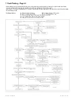
Page 40: ... in Routine Maintenance b Lower the control panel assembly by undoing the securing screw at the top right hand side of the control panel c Note how they fit and remove the four connectors from the transformers d Remove the two screws retaining the transformer to the back panel and remove transformer from appliance e Fit the new transformer assembly in reverse order ...

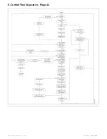
Page 41: ...lt component see Section Component Replacement To assist in fault finding the logic sequence of the electronics control circuit precedes the fault finding charts Preliminary Actions A Set Boiler Switch to Stand by B Set Heating Switch to OFF centre C Set C H Temp Control to MAX D Turn OFF all Hot Water Taps E Ensure all isolating valves at the base of the appliance are OPEN F Turn ON EXTERNAL GAS ...

Page 42: ...42 Control Flow Sequence Part No 27 20334 8 Control Flow Sequence Page 42 ...

Page 43: ...Part No 27 20334 Functional Flow 43 9 Functional Flow Page 43 ...

Page 44: ...44 Pictorial Wiring Diagram Part No 27 20334 10 Pictorial Wiring Diagram Page 44 ...

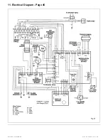
Page 45: ...Part No 27 20334 Electrical Diagram 45 11 Electrical Diagram Page 45 ...

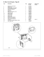
Page 46: ...ly 1 10 20162 6 Transformer 1 21 19646 7 Electrode 1 10 20179 8 Pressure Relief Valve 3 bar 1 10 18828 9 Gas Valve SIT 1 10 18682 10 Pressure Gauge 1 10 18769 11 Burner Injector 3 22 20207 12 Air Flow Switch 1 10 18752 13 Diverter Valve 1 10 20319 14 Fan Assembly 1 10 18750 15 Electrode Lead Assembly 1 21 19660 16 Detection Lead Assembly 1 21 18840 17 Flow Temperature Sensor 1 10 18761 18 O Rings ...

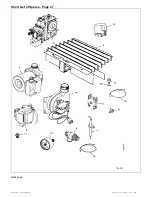
Page 47: ...Part No 27 20334 Short List of Spares 47 Short List of Spares Page 47 Back page ...

Reviews: