15.0 Changing Components
45
© Baxi Heating UK Ltd 2011
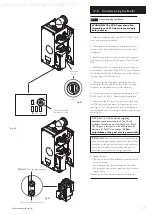
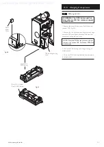
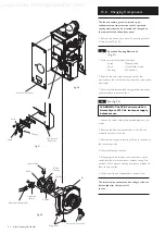
15.4
PCB
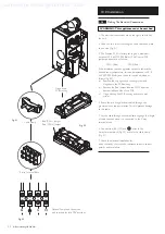
(Figs. 48 & 49)
WARNING: The PCB Control and Fan
Assembly are 325 Vdc. Isolate at supply
before access.
1. Remove the plastic button cover. Refit them onto
the new PCB (Fig. 48).
1. Remove the top right hand securing screw and hinge
down the PCB housing and disconnect the electrical
connections noting their positions
NOTE: Check the PCB for the presence of input
jumpers - see section 10.8. Set the new PCB as the
one removed.
2. Lift Control PCB housing out of hinge housing of
metal bracket.
3. Fit the new PCB Housing Assembly and reassemble
in reverse order.
PCB Housing Securing
Screw
Fig. 48
Blue (CN11) Jumper
Red (CN12) Jumper
Fig. 49
Hinge down
PCB Housing
Plastic
Button
Cover
Supplied by HeatingSpares247.com

