Component Replacement - Page 36
6.16
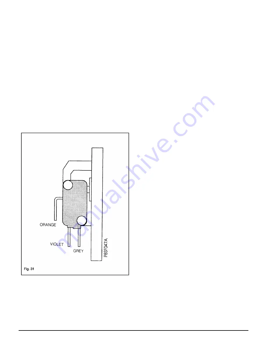
Air Pressure Switch
(Fig. 20 & 31)
a.
Remove the white front case, base panel and white right
hand side panel. See 5.1, 5.2 & 5.3 in 'Routine
Maintenance'.
b.
From the top right hand side of the boiler undo the
securing screw retaining the pressure switch /bracket
assembly
c. Lift the pressure switch / bracket assembly clear of the
top of the boiler. Note positions and disconnect pressure
tubes and electrical connectors.
d.
Replace pressure switch and re-assemble in reverse
order.
Note:
The Red pressure tube must be connected to the High
side of the switch, indicated by (H) and a Red Paint Spot.
The electrical connections must be as follows.-
Orange
Common
(C)
Violet
Normally Closed
(NC)
Grey
Normally Open
(NO)
6.17
Fan
a.
Remove the fan. See 5.1, 5.2, 5.3 & 5.4 in ‘Routine
Maintenance’.
b.
Transfer the fan outlet seal to the new fan and fit the fan
into the appliance. Ensure a good seal is made between
the fan inlet and the fluehood.
c.
Re-assemble in reverse order. Ensure the seal is not
trapped on the turned down edge.
6.18
Fan Seals
a.
Remove the fan. See 5.1, 5.2, 5.3 & 5.4 in ‘Routine
Maintenance’.
b.
Remove the fan outlet seal by sliding the seal off the
fan. Remove the fan inlet seal by pulling the seal away
from the fluehood and disconnecting the pop in locaters.
c.
Fix the new seals in position.
d.
Re-assemble in reverse order. Ensure the seal is not
trapped on the turned down edge.
6.19
Temperature Sensor D.H.W. & C.H.
(Fig. 20)
a.
Remove the white front case and base panel.
See 5.1 & 5.2 in ’Routine Maintenance’.
b.
For D.H.W sensor lower the control panel assembly by
undoing the securing screw at the top right hand side of
the control panel.
c.
Before removing the hot water or central heating sensor,
first close the isolating valves for the circuit involved and
drain the appliance.
For C.H,
with both 22mm isolating valves closed, reduce
the system pressure by opening the pressure relief valve
and drain the water from the heating circuit by removing
the drain plug from the undersideof the pump manifold.
For D.H.W
, close the 15mm cold water isolating valve,
open the lowest hot water tap, then remove theD.H.W
drain screw on the isolation valve to fully drain the
appliance (Fig. 16).
d.
Disconnect the electrical connection from the sensor(s)
and unscrew from its housing.
e.
Refit the new sensor(s) and 'O' Ring seal if required. Re-
assemble in reverse order. If necessary (C.H. sensor
only) re-charge the central heating system as described
in section 1.6 and check for leaks.
6.20
Pressure Gauge
(Fig. 20)
a.
Remove the white front case and base panel.
See 5.1 & 5.2 in ’Routine Maintenance’.
b.
Close the central heating isolating valves, reduce the
system pressure by opening the pressure relief valve,
then drain the water from the appliance by removing the
drain plug located under the pump manifold.
c.
Use a spanner to prevent the pressure gauge from
rotating and undo the 1/4" BSP nut behind the pressure
gauge and remove the gauge.
d.
Fit the new pressure gauge, in its correct position.
Re-assemble in reverse order. Use the new washer to
seal. Re-charge the central heating system as described
in section 1.6 and check for leaks.
Summary of Contents for 80e
Page 5: ...Optional Extras Page 5 ...
Page 6: ...Optional Extras Page 6 Installation instructions included as necessary with each kit ...
Page 7: ...Optional Extras Page 7 Installation instructions included as necessary with each kit ...
Page 12: ......
Page 28: ...Routine Maintenance Page 27 ...
Page 30: ...Routine Maintenance Page 29 ...
Page 34: ...Component Replacement Page 33 ...
Page 35: ...Component Replacement Page 34 ...
Page 43: ...7 1 Control Flow Sequence Permanent Pilot Page 42 ...
Page 44: ...7 2 Functional Flow Permanent Pilot Page 43 ...
Page 45: ...7 3 Fault Finding Permanent Pilot Page 44 ...
Page 46: ...7 4 Electrical Diagram Permanent Pilot Page 45 ...
Page 47: ...8 1 Control Flow Sequence Electronic Page 46 ...
Page 48: ...8 2 Functional Flow Electronic Page 47 ...
Page 49: ...8 3 Fault Finding Electronic Page 48 ...
Page 50: ...8 4 Electrical Diagram Electronic Page 49 ...


