background image

22

OBM-N/L/R Series

Professional Video Monitor

Outstanding Picture Quality

Page 6/8

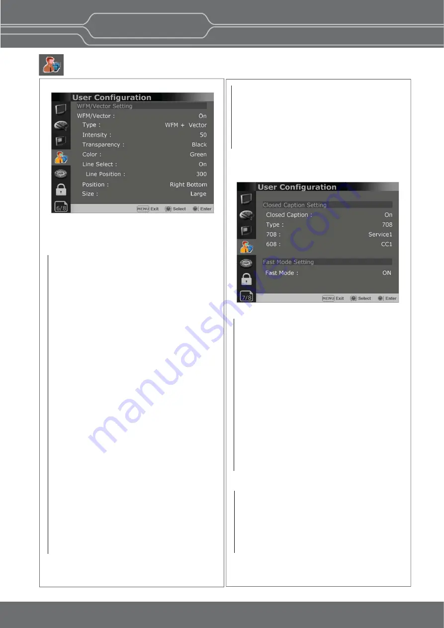
WFM/Vector Se ng

       *[WFM/Vector] func on works in SDI input only.
       

WFM/Vector

      - Select [On] to display the [WFM/Vector] and [Off]
       not to display.
    

Type

     - Sets to ac vate and deac vate Waveform 
       monitor and Vectorscope.
       You can select from among [WFM], 
       [VectorScope], [WFM+Vector], [WFM Wide].


Intensity

       Adjusts the brightness of Waveform and 
       Vectorscope display.  
       You can select from 1 to 64.
    

Transparency 


       Adjusts the transparency level of Waveform and 
       Vectorscope.    
      [Black]: The background is black. Displayed image 
                   is hidden behind the background.
      [Half]: The background is transparent. Displayed
               image can be seen indis nctly behind the
               Waveform and Vectorscope display.
    

Color

      Selects the color of Waveform monitor.
      Available colors are [Green] and [White].
    

Line Select

      Selects [On] to display the Waveform of the line
      assigned in [Line Posi on] below.      
       *

Line Posi on

         Selects the specific horizontal line for 
         Waveform and Vectorscope.
         Increases the value to move the line upwards 
         and decreases the value to move the line 
         downwards.


User Configuration Menu

Page 7/8

Closed Cap on

   Selects [On] to display the Closed Cap on and 
   [Off] not to display.

Type

   Sets the Closed Cap on type.
   [708]: Selects this mode to display 708 when
               HD-SDI signal is input.
    [608(VBI)]: Selects this mode to display 608(VBI)
                         when SD-SDI signal is input.
    [608(708)]: Selects this mode to display 608(708)
                         when HD-SDI signal is input.

708

    Sets the Closed Cap on type for 708.
    Selects from [Service1] to [Service6].

608

    Sets the Closed Cap on type for 608(708) and
    608(VBI). Selects from [CC1] to [CC4].

Closed Cap on Se ng

Fast Mode Se ng
   

- This func on minimizes the internal video 

     processing  me from the signal input to the 
     display on the screen.
   

Fast Mode


Selects [On] to ac vate Fast Mode and [Off] to 

      turn it off.

Posi on

  - Sets the display posi on of the [WFM/Vector].
    Selects [Right Bo om], [Le  Bo om],[Le  Top], 
    or [Right Top].    

Size

  -Sets the size of Waveform and Vector Scope.
        [Large] and [Small] can be selected.

** OBM-N240 doesn’t support Fast Mode.

Summary of Contents for OBM-L Series

Page 1: ...Operational Instructions OBM N170 OBM N180 OBM N210 OBM N240 OBM N310 OBM N420 OBM N460 OBM N550 OBM L180 OBM R210 User Manual Ver18 3 OBM N L R Series Professional Video Monitor...

Page 2: ...ion of Parts and Controls Front Panel Rear Panel 4 Using the Menu 5 Adjustment Using the Menus 6 OSD Menu Operations Status Menu Color Temp Color Space Gamma Menu Camera Assist Menu User Configuration...

Page 3: ...ded by the manufacturer please check the proper load capacity or current capacity and use an adapter with stable voltage Do not overload AC outlets or extension cords Overloading can cause re or elect...

Page 4: ...es and can radiate radio frequency energy and if not installed and used in accordance with the instruc on manual may cause harmful interference to radio communica ons Opera on of this equipment in a r...

Page 5: ...out Custom 3D LUT File Import Through USB Gamma Selec on 1 0 3 0 Color Temperature 3200K 5500K 6500K 9300K USER 1 2 3 D CINEMA HDR Camera log Compare Side by Side Wipe Posi on Waveform VectorScope Wav...

Page 6: ...anges in the order of Composite Component DIGITAL Bu on Lamp Press the bu on to select Digital input Mode changes in the order of HDMI DVI OBM L180 SDI Bu on Lamp Press the bu on to select SDI input H...

Page 7: ...rease it CHROMA knob Press this knob to display the adjustment screen and adjust the color intensity Press again to hide the adjustment screen Turn the knob right to increase the color intensity and t...

Page 8: ...h and Indicator Press to turn the power on when this monitor is in standby mode A er being turned on the monitor performs ini aliza on and the indicator ashes in green Press the switch again for a sec...

Page 9: ...9 Rear Panel A B C D F E H I G A D F I G OBM N L R Series Professional Video Monitor Outstanding Picture Quality OBM N170 N180 N210 N240 N310 N420 N460 N550 R210 OBM L180 B...

Page 10: ...nput connectors Input connector for HDMI signals E DVI D Input connector Input connector for DVI signal F PARALLEL REMOTE connector RJ 45 8 pin Forms a parallel switch and controls the monitor externa...

Page 11: ...in connec on using the LAN input output connectors enables the control of mul ple monitors in sequence I AUDIO IN connector Stereo mini jack Connector for analog audio input Analog input can be select...

Page 12: ...menu is displayed on the right 4 Make the se ng or adjustment on an item How to change the adjustment level To increase the level turn the SELECT VOLUME knob right To decrease the level turn the SELEC...

Page 13: ...us Assist Time Code Volume SDI Input SDI Payload ID Model Name Serial Number Board Version Opera on Time Last Calibra on Time Iden er Sampling Picture Rate Scanning Method Bit Depth Link Assignment R...

Page 14: ...Mode Se ng Fast Mode System Se ng Time Code Time Code Posi on Size Display Reference Size Transparency Peak Hold Time Display Type Variable Aspect 3G Signal Format RGB Range Internal Pa ern Key LED O...

Page 15: ...Level Meter Focus Assist Time Code Volume SDI Input SDI Payload ID Iden er Sampling Picture Rate Scanning Method Bit Depth Link Assignment When the SDI signal is connected these items are displayed Fo...

Page 16: ...000 cd m is clipped ST 2084 10000 The characteris cs of LCD panel doesn t allow to produce the ideal brightness required by this standard so the gamma is displayed in the rela ve brightness HLG 0 98 3...

Page 17: ...nd push Enter in Import Log Data menu the data is saved to the monitor The le name of the user log data is displayed on the OSD up to 15 characters and the log data le should be placed on the top fold...

Page 18: ...elects a color for Focus Assist among Red Green Blue White Yellow Cyan Magenta Frequency Adjusts the edge di erence level between the edges in an image Available values are from 0 to 100 Color red yel...

Page 19: ...um 20 Gamut Error User Configuration Menu User Con gura on consists of the adjustment menus such as User Preset Se ng Func on Bu on Se ng Input Se ng Speaker Out Audio Level Meter Se ng Marker Se ng W...

Page 20: ...r Reference Selects the default value of Audio Level Meter Size Transparency Selects the size and transparency of Audio Level Meter Normal Half Large Full Large Half Peak Hold Time Controls the speed...

Page 21: ...U Ac on 4 3 EBU Graphic 4 3 Color Selects the color of the marker You can select from among White Gray Red Green Blue Yellow Cyan Magenta Aspect Mat Darkens the outside of the area of the Aspect Marke...

Page 22: ...on Selects the speci c horizontal line for Waveform and Vectorscope Increases the value to move the line upwards and decreases the value to move the line downwards User Configuration Menu Page 7 8 Clo...

Page 23: ...lay the LTC me code Time Code Posi on Size Allows to adjust the size and posi on of the Time Code Top Large Top Small Bo om Large Bo om Small can be selected System Se ng SD SDI HDMI Example HD 3G SDI...

Page 24: ...Se ng The monitor supports TSL UMD Protocol V3 1 V5 0 provided by Television System Ltd Transparency Text Color Le Tally Color The monitor displays English alphabet numbers Symbolic codes Up to 16 cha...

Page 25: ...ini al password is 0000 When you use Password change the ini al password rst User Parameter Lock Selects On to protect the se ng values Selects O to not protect by the password User Preset Lock is th...

Page 26: ...10bit 4 4 4 YCbCr 10bit 4 4 4 RGB 12bit 4 4 4 YCbCr 12bit 1280x 720 23 98 24 25 29 97 30 50 59 94 60p 4 4 4 RGB 10bit 4 4 4 YCbCr 10bit 2048 x1080 48 50 60p 2048 x 1080 23 98 24 25 29 97 30p Psf 4 4 4...

Page 27: ...ybrid Log Gamma and S Log3 OBM HDR provides the func on of comparing HDR and SDR Standard Dynamic Range on the displayed image on the OBM series simultaneously Gamma 1 8 Gamma 2 4 Adjustable Gamma Gam...

Page 28: ...lack level and without a ec ng mid tones False Color This func on evaluates the Luma Y level of the input image If the certain Y level is set the pixels with the designated Luma Y level are displayed...

Page 29: ...on the target color space which the user selects The default values of Y Maximum Minimum Chroma Maximum Minimum RGB Maximum Minimum are in compliance with EBU R 103 standard And the values can be adj...

Page 30: ...and tally informa on can be displayed on the screen with an external remote func on via Ethernet The TSL system protocol is supported The color of the source name and tally color can be selectable am...

Page 31: ...t color matching between indivisual displays as well as using customized looks that have been createcl by 3rd party color grading applica ons 32 33 64 and 65 cube le is supported HDR Camera Log Compar...

Page 32: ...60 Line In Stereo H P Out Front Stereo GPI 7 Port RJ 45P Jack RS 422 Jack RJ 45P Input Output For Firmware Update Color Calibra on Power Cable Rack Mount Kit Carrying Case Sun Hood Acrylic Protector...

Page 33: ...2 HDMI 1 3a Analog YPbPr Composite DVI D 3G HD SD SDI 1 2 1080p 60 59 94 50 30 29 97 25 24 23 98 30sF 29 97sF 25sF 24sF 23 98sF 1080i 60 59 94 50 1080p 30 29 97 25 24 23 98 24sF 23 98sF 1080i 60 59 94...

Page 34: ...29 97sF 25sF 24sF 23 98sF 1080i 60 59 94 50 1080p 30 29 97 25 24 23 98 24sF 23 98sF 1080i 60 59 94 50 720p 60 59 94 50 1920 x 1035i 60 59 94 2048 x 1080p 24 23 98 24sF 23 98sF 480i 59 94 576i 50 1080...

Page 35: ...MI 1 x DVI 1 x Phone Jack In 1 x Phone Jack Out 2 x Speaker Out Size Resolu on Pixel Pitch Color Viewing Angle Luminance of White Contrast Display Area H x V 1 x Ethernet 1 x GPIO 2 x Serial 1 x USB P...

Page 36: ...Rack Mount Kit VESA Mount Wall Brackt BNC SDI HDMI BNC YPbPr BNC CVBS DVI BNC SDI SMPTE ST 425 AB SMPTE ST 274 SMPTE ST 296 SMPTE ST 260 SMPTE ST 2048 SMPTE ST 125 ITU R BT 656 HDMI DVI D 1 x Phone Ja...

Page 37: ...208 Building A Samsong Techno Valley 140 Tongil ro Deogyang gu Goyang si Gyeonggi do Korea 10594 Tel 82 2 354 6055 Fax 82 2 354 6056 E mail sales postium com www postium com...

Reviews: