background image


Part 20

PRINTER 

One of the major design features of the PST terminals is the ability to 

accommodate a very large range of printers. The terminal provides a printer 
platform where the printer can be mounted (use the Velcro strips in the 
accessories kit for fixation aid), and also provides a regulated 24 volts DC 
power line to power the printer. 

The terminal can accommodate both parallel and serial interfaces. 
Please consult the printer user manual before assembling and 

connecting any printers to the terminal. 

USB 

There are two standard USB female connectors in the rear room. Both 

support the Universal Serial Bus Specification standard 2.0 and also 1.1. 

SYSTEM PROTECTION 

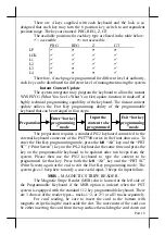
In the Posiflex POS system delivered with preloaded OS, there is a 

function built in for system protection. A screen as below will pop up for a 
short period of time in operation system booting up stage. 

In normal practice, nothing 

has to be done and the system boot up 
continues. However, this function is 
useful for our end users to fight 
against virus attacks or malicious 
system invasions nowadays or even 
some possible system crash. Please 
connect a PS/2 keyboard to KB port of 
the system to engage this function if 
there in no specific instruction from 
your system integrator. Press the three key combination of “Ctrl” + “Alt” + 
“F12” at the above screen or press the key on programmable keyboard per 
your system integrator’s arrangement. 

Please follow screen display to refresh the system back up then you 

can call for instruction on system  restore from your system integrator once the 
disaster occurs. 

警告使用者


這是甲類的資訊產品,在居住的環
境中使用時,可能會造成射頻干
擾,在這種情況下,使用者會被要
求採取某些適當的對策。


T31454 

Summary of Contents for PST - 7700

Page 1: ...ng without limitation loss of data or profits resulting from the furnishing performance or use of this material This information is provided as is and Posiflex Inc expressly disclaims any warranties expressed implied or statutory including without limitation implied warranties of merchantability or fitness for particular purpose good title and against infringement The information in this manual co...

Page 2: ...ole system till completely exhausted Repeatedly using it up or improper maintenance reduces the battery life dramatically Always fully recharge the battery at least once every 3 months if the battery is not connected Always disconnect the UPS battery from the system if the system is to be left OFF for more than 72 hours to prevent possible damage Only connect the UPS battery back right before you ...

Page 3: ...ided the wiring spaghetti associated with more traditional PC solutions This Open Standard Architecture ensures that this terminal can use the PC application software and development tools that are now inexpensively available and abundant The terminal may be used as a self contained unit or by using the integrated network interface as one of several terminals in a network system controlled by a ba...

Page 4: ...xists COM1 is capable of providing a 5 V DC supply COM2 COM3 and COM4 each are capable of providing independently a 5 V DC or a 12 V DC supply All these DC supplies are achieved through internal jumper setting and they are all defaulted to give no DC supply at delivery Parallel Port Each PST system is equipped with a parallel port that supports SPP EPP ECP USB Device Connection The PST7700 series ...

Page 5: ...already purchased PST product h Integrated FDD 3 5 1 44 MB i Power management kit with CR port The most advanced UPS functions to safeguard the POS operation against intermittent power failure with another option UPS battery careless touch on the power switch unmanned remote account consolidation operation etc j 2 in 1 Cash Drawer Control Cable Cable CCBLA 238 when added to the optional CR port of...

Page 6: ...e dependent accessories as listed below l Recovery CD for preloaded OS or Posiflex Product Information CD for driver utilities without OS l Cable tie 5 pieces l VFD terminator 1 piece l COM1 terminator 1 piece l Main power cord 1 piece The content of keyboard type dependent accessories is listed below Please note that these parts are different in size between the KB112 for PST7700 PST7705 and the ...

Page 7: ...is ordered Connect the cable through the opening on the wall toward the rear room of the cabinet to the connector in the rear room Always disconnect the UPS battery when the system is to be left powered off for more than few days Please pay particular attention to the environment requirement for UPS battery in next chapter USING THE PST SYSTEM CRT MONITOR Upon receiving the CRT type PST7700 the mo...

Page 8: ...unted To remove the monitor first disconnect the cable then pull the latch on the underside of the cable cover to remove the cable cover Then pull the monitor hook lever at rear bottom of the bowl by finger then raise and rotate the monitor forward till the CRT front is facing downward LCD CASHIER DISPLAY When the PST7705 or PST7735 is ordered the user has to take the 12 1 TFT LCD cashier display ...

Page 9: ...ustomer display or VFD Please remove the VFD terminator from this connector and store in a safe place Insert the cable plug of the customer display into customer display connector until a click sound is heard Please NOTE The VFD connector must always be populated either with the VFD terminator or a plug from the customer display Failure to do this will prevent COM1 from working correctly Close the...

Page 10: ...o so could result in permanent damage Please note that on at least one side of the square stem of the key top there is a small latching tab to match with a corresponding tab on the bottom inner side of the guide hole as in the example drawing above The system integrator can program the content of the keyboard for the application software following the technical guidance of Posiflex keyboard progra...

Page 11: ...or internally connected KB wedge device is done We strongly advise users to consult with their dealers to have an authorized technician for such installation PRINTER Assemble the printer following the instructions supplied with the printer Remove the battery cover as in UPS battery section The user may find the UPS battery lying in the battery compartment if this option is ordered Connect the prin...

Page 12: ...t has a 6 pole plug at one end and two 8 pole plugs at the other The 6 pole plug should be inserted in the connector marked CR found in the rear room of the terminal Each 8 pole plug should be inserted into the connector marked signal cable from POS Printer at the rear of one of the cash drawers The cable lengths for the two 8 pole plugs are different Use the shorter one for the original cash draw...

Page 13: ...efinitely observe the alerts in beginning of this manual If the equipment is to be powered off for more than few days please always disconnect the battery from the system Reconnect it and turn on the system to recharge the battery for 1 2 hours every 3 months for temperature lower than 30 C Recharge for 1 2 hours every month for temperature over 30 C Temperature above 40 C must be strictly avoided...

Page 14: ...connector and is supported by the UPS function if the power management option is installed The video memory of this port shares the system memory The video memory size can be set in the CMOS setting to match the user s application Customer Display Port The customer display connector must always be occupied either by the terminator plug as supplied or by one of the family of Posiflex customer displ...

Page 15: ...uch that the main power to the system may be controlled by many methods as below 1 Hardware power switch 2 Software OFF command 3 Automatic power ON control 4 Emergency power OFF Switching from OFF to ON requires a normal supply of the AC power Hardware Power Switch This button is located on the lower right hand front edge of the keyboard and can be used to turn the system on and off alternatively...

Page 16: ...ed off It will take about 4 seconds if no power management kit installed and it takes about 10 seconds if the option installed If there appears to give a special coded beep tone in the pattern short long short long short prior to the system power off in this process please remove the AC power and wait for few minutes to allow the hardware registers to reset If there is no such beep AC removal is n...

Page 17: ...on switch The horizontal rotation is almost 360 degrees for any required viewing direction The up down tilt of PD 2201 PD 2301 and PD 7201 provide 2 different view angles 14 5 and 30 However there are 8 viewing angles for PD 101 ranging from 2 5 to 60 PROGRAMMABLE KEYBOARD The standard programmable keyboard for PST7700 7705 is a 8 x 14 matrix layout keyboard coded as KB112 The keyboard for PST7730...

Page 18: ...T7700 series in the front door area To enter the Hot Key programming mode press the left Alt key and the PRT SC Print Screen key on the PS 2 keyboard at the same time and press the key on the programmable keyboard to be updated after two beeps from the system Please then use the PS 2 keyboard to type the content to be programmed for that key Press both the left Alt key and the PRT SC Print Screen ...

Page 19: ...l 1 44MB 3 5 Floppy Disk Drive FDD behind the door EXTERNAL PC KEYBOARD From time to time it will be necessary or more convenient to use a standard PC keyboard This may be to reprogram the PST keyboard key definitions or to alter some aspects of either the DOS operating system or the application program The PC keyboard may be plugged into the 5 pin DIN socket behind the front door This socket may ...

Page 20: ...eloaded OS there is a function built in for system protection A screen as below will pop up for a short period of time in operation system booting up stage In normal practice nothing has to be done and the system boot up continues However this function is useful for our end users to fight against virus attacks or malicious system invasions nowadays or even some possible system crash Please connect...

Reviews: