background image


Part 6 

Fixing pole display base to system 

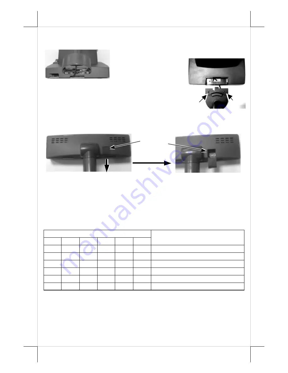
To fix the PD-2602 to base of KS or TP systems, please connect the 

interface cable of PD-2602 through the cable exit 
in base as in 

Pix. 9

   a 

peeping view of pole 
display joint base bottom 
to the appropriate port  in 
main unit  passing the 

inside of system base as indicated in the top-view 
picture 

Pix. 10

. Match the pole base (joint mechanism) 

to the system rear connect area Fit 2 screws 

through 

washers

 at arrowed points to hold the joint tight. 

COMMAND EMULATION MODE SETUP 


Now please check the back of PD-2601 / 2602 display head as in the 

left picture  in 

Pix. 11

. There is a small piece of plastic cover for the “DIP 

switch window”. Slide the cover downward but don’t pull it off otherwise you 
may have to practice for inserting it back. You can find 6 positions of DIP 
switches in this window. Adjust for the appropriate command mode used by 
the application program according to below table. Switch position counts from 
left to right and “ON” means pushed up as indicated in the right part in 

Pix. 11

Switch Position 

Command Mode 

ON 

OFF  OFF 

ON 

OFF  OFF 

ADM 

ON 

OFF 

ON 

ON 

OFF  OFF 

Aedex 

ON 

OFF 

ON 

OFF  OFF  OFF 

Epson 

ON 

OFF  OFF 

ON 

ON 

OFF 

Futaba 

ON 

OFF 

ON 

OFF 

ON 

OFF 

Noritake 

ON 

OFF 

ON 

ON 

ON 

OFF 

UTC 

The factory default command mode is set to Noritake mode for 

normal delivery. Please change it to Epson mode if OPOS or UPOS driver is 
used for the application program. 


Pix. 9 

Pix. 10 

DIP switch 
window 

Pix. 11 

Summary of Contents for PD-2601 Series

Page 1: ...ing without limitation loss of data or profits resulting from the furnishing performance or use of this material This information is provided as is and Posiflex Inc expressly disclaims any warranties expressed implied or statutory including without limitation implied warranties of merchantability or fitness for particular purpose good title and against infringement The information in this manual c...

Page 2: ...less touch POS terminals or TP series touch POS terminals Two line display with 20 characters per line Adequately large characters for easy viewing 9 03 mm by 5 25 mm Long life and trouble free operation 15 30 and 45 adjustable viewing angles Total height 486 or 386 mm PD 2601 on HT and PB series Total height 330 mm PD 2602 on base of KS and TP series Display framecan rotate horizontally270 freely...

Page 3: ...system has to be opened with sufficient precautions First push in the circled knobs on both sides as in Pix 1 to remove the back cover Take out the arrow pointed pole cover from it Opening the top cover of system Prepare a piece of clean soft clothe of appropriate size in front of the HT system to prevent damage Turn the display panel to straight up position For both HT and PB system push in the r...

Page 4: ...cking lugs A in Pix 3 facing left and now insert the 2 bottom locking lugs A on base unit into the 2 rectangular installation holes A on bottom of HT or PB chassis from the right corner with the pole display slightly inclined to the left as in Pix 4 Please note that both bottom locking lugs A should be completely inserted and come out of the bottom plate of HT or PB system as emphasized by an arro...

Page 5: ... chassis Only 1 screw needs to be applied Use the self tapping screw that comes with PD 2601 to fix from external side of sidewall as demonstrated in Pix 6 Connect interface cable Carefully close back the top cover of HT or PB system and connect the interface cable of PD 2601 to appropriate port in system connector area Then close the back cover of the system INSTALLING PD 2602 Opening the rear co...

Page 6: ...ece of plastic cover for the DIP switch window Slide the cover downward but don t pull it off otherwise you may have to practice for inserting it back You can find 6 positions of DIP switches in this window Adjust for the appropriate command mode used by the application program according to below table Switch position counts from left to right and ON means pushed up as indicated in the right part ...

Page 7: ...installed and with COM port power set for serial models turn on the HT or KS or TP Posiflex POS system a firmware identifier as power on sign will appear on the pole display screen for a while to indicate that pole display is self tested O K and ready to work ...

Page 8: ...E SELECTION GUIDE The below table provides some comparison for selection on command mode to be used in the application program if it is not yet determined Mode ADM Aedex Epson Futaba Noritake UTC Cursor N A N A Invisible Blinking Block Blinking Block Blinking Block DP Default mode N A N A Over W V scroll Over W PT User defined font N A N A 2 chars N A 2 chars 2 chars PT Brightness control NO NO YE...

Page 9: ... system 5VDC 1A ENVIRONMENTAL Operating temperature 0 to 40 C Storage temperature 20 to 70 C Operating humidity 20 to 85 non condensing Storage humidity 5 to 90 non condensing WARNING If the user opens the pole display housing to make any modification all the product warranty will be voided NOTE Please refer to Posiflex Product Information CD or visit our web http www posiflex com twfor further in...

Page 10: ...Multi lingual 03 3 PC860 Portuguese 04 4 PC863 Canadian French 05 5 PC865 Nordic 06 6 Russian 07 7 Albic 13 19 PC858 Euro FD 253 PC437G Greek FE 254 Win1257 Windows Baltic FF 255 Win1253 Windows Greek The list of commands available in each mode can be found in the appendix 警告使用者 這是甲類的資訊產品 在居住的環 境中使用時 可能會造成射頻干 擾 在這種情況下 使用者會被要 求採取某些適當的對策 T31454 ...

Reviews: