background image


Part 3 

V.  HARDWARE INSTALLATION 

A. 

VGA Port Power Preparation 

1.  Inquire for technical support from your dealer to set the power support in 

the VGA port of the FT system following the relevant Technical Manual 
of the FT system. Please note that once the VGA port is no longer to be 
occupied by the LM-6601, this 

power support must be discontinued!


B. 

Fix Bracket onto LM-6601 

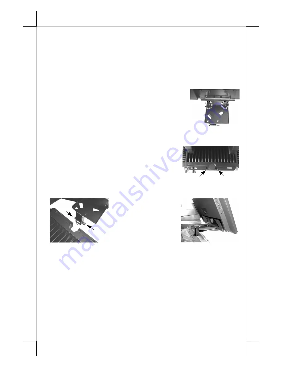
2.  Unfold down the semi-circular base tongue of the 

LM-6601 main unit and apply the L shape bracket 
on this base tongue. Use the 2 screws in the 
accessory bag to fix the bracket over the base 
tongue as circled in the right picture. Note that the 
slots for the screws on the bracket allow some 
adjustment on position of LM-6601 for application. 

C. 

Open Back Cover & Pole Cover of FT System 

3.  Refer to the User’s Manual of the FT system 

about  “INSTALLING BASE MOUNT KIT” to 
open back cover and remove the 2 arrowed 
screws to remove the pole cover. Preserve the 2 
screws for the next step. 

D. 

Install LM-6601 to FT System 

4.  Install the slender part of the L shape bracket to the hole for pole cover 

and screw it to top 
cover of FT base 
tightly at the arrowed 
holes as in the left 
picture and result is 
shown at the right. 


E. 

Cable Connection 

5.  Connect the VGA cable that has both 3 x 5 D sub male ends to VGA port 

at rear of LM-6601 and the VGA port of host system. Screw in the cable 
to connectors at both ends. 

F. 

Driver Installation 

6.  There is no need to install driver for use of LM-6601. However, the 

supported display modes are tabulated at last part of this manual 


Summary of Contents for LM-6601

Page 1: ...n the authorized technicians The user should consult his her dealer for the problem happened Warranty voids if the user does not follow the instructions in application of this merchandise The manufacturer is by no means responsible for any damage or hazard caused by improper application ABOUT THIS MANUAL This manual assists the user to utilize the LCD Monitor LM 6601 Thos series provides adjustabl...

Page 2: ...r LM 6601 onto FT system 3 User s Manual 4 VGA Cable 21863241710 5 Fixing Screws 10684038123 6 32 12L x 2 III PARTS IDENTIFICATION IV STATUS LED INDICATION Green standby Blue operating Display Panel OSD Button LM 6601 Status LED NEXT Button L Shape Support Bracket FT System Back Cover Power Switch Button Button ...

Page 3: ... adjustment on position of LM 6601 for application C Open Back Cover Pole Cover of FT System 3 Refer to the User s Manual of the FT system about INSTALLING BASE MOUNT KIT to open back cover and remove the 2 arrowed screws to remove the pole cover Preserve the 2 screws for the next step D Install LM 6601 to FT System 4 Install the slender part of the L shape bracket to the hole for pole cover and s...

Page 4: ...to activate the OSD functions On Screen Display adjustment The OSD window will pop up on the screen On top part of this window is a Posiflex logo with the OSD firmware version indicated to its lower right Below this area is a row of icons for main OSD menu Below the main menu is a group of icons for submenu that corresponds to one icon selected in the main menu An analysis of the video signal on r...

Page 5: ... select item or return to main menu Press NEXT button to select among auto color adjust auto RGB reset Color balance adjust and exit AUTO COLOR ADJUST Upon an OSD button press on this icon the monitor will perform an automatic color adjustment and exits the OSD window leaving 2 icons below at center of the screen Press NEXT button to switch the selection Press OSD button to make the choice ACCEPT ...

Page 6: ...are 6 icons in this submenu Press OSD button to select item or return to main menu Press NEXT button to select among auto geometry adjust horizontal size phase horizontal position vertical position and exit AUTO GEOMETRY ADJUST Upon an OSD button press on this icon the monitor will perform an automatic geometry adjustment and exits the OSD window leaving 2 icons below at center of the screen Press...

Page 7: ...cons in this submenu Press OSD button to select item or return to main menu Press NEXT button to select among OSD time OSD horizontal position OSD vertical position and exit OSD TIME When this item is selected there will be only the OSD time icon with an adjustment indication bar under it between the main menu area and the video signal mode Press or button to adjust the waiting time for OSD operat...

Page 8: ... decrease sharpness Press to go the other way Press OSD button to save the current setting and return to OSD submenu MODE SELECT Pressing OSD button on this icon will have no effect at all if the display mode is not one of the confusing modes The confusing modes here mean 640 x 400 or 720 x 400 in display resolution as both mode have refresh rate of 70Hz horizontal frequency of 31 5KHz and pixel f...

Page 9: ...ange on middle of screen Maximum supported color depth is 18 bits or 262 144 colors Supported display modes are as in the table Display Resolution Refresh Rate Hz Horizontal Frequency KHz 640 400 70 31 5 60 31 5 72 37 9 640 480 75 37 5 720 400 70 31 5 56 35 1 60 37 9 72 48 1 800 600 75 46 9 60 48 4 70 56 5 1024 768 75 60 ...

Page 10: ...Part 10 警告使用者 這是甲類的資訊產品 在居住的環 境中使用時 可能會造成射頻干 擾 在這種情況下 使用者會被要 求採取某些適當的對策 T31454 ...

Reviews: