background image


Page 4 


B.


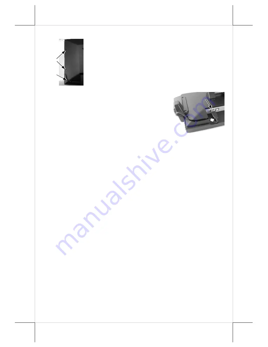
Side Mount Upgrade Kit 

When a side-mount upgrade kit option SD-300 is ordered 
with  the  TM-2212,  this  option  is  already  installed  in  the 
delivery.  To  assemble  a  separately  delivered  kit  to  the 
monitor,  please  use  the  2  attached  screws  with  washer  to 
fix  the  kit  to  right  side  of  LCD  panel  from  back  as  the 
picture in the left. After fix these two screws, please route 
the USB cable into the winding slot. 

 
No matter the kit is SD-300 or whether the kit itself 
contains MSR only, finger print sensor only or both 
options,  the  kit  utilizes  a  USB  cable.  Connect  it  to 
the  USB  port  at  right  side  of  the  I/O  port  of  TM-
2212 and insert it in the as picture at right.  
 

VI.  DRIVER INSTALLATION 

A. 

INSTALLATION 


USB touch


The USB interface touch controller operates as an USB mouse without need 
for any special driver in Windows. However, there is a program supported for 
its calibration and touch function manipulation. Please find it in the attached 
Posiflex product information CD-ROM under subdirectory 
\Drivers\TM_LM\USB or select “Peripheral Drivers & Utilities” --> “USB 
Touch Manager” in version 3.0 or later of Posiflex product information CD to 
install it. 
 
For Linux environment, please find the setup program for the suitable kernel in 
the  same  directory  and  install  the  required  driver  and  calibration  program  as 
the setup program proceeds. 
 

B. 

SETUP/CALIBRATION 


USB touch manager 

Once the USB control program is installed, the  user can  utilize it to calibrate 
the  touch  screen,  define  mouse  button  emulation  parameters,  enable  right 
button  emulation  or  define  the  click  sound’s  tone  and  duration.  Please  go  to 
“Program  Files”  and  select  “Posiflex  USB  Touch  Tools”  and  then  select 
“Posiflex  USB  Touch  Manager”  within  the  tools  to  engage  this  utility.  Most 
items  in  this  utility  should  be  easily  understandable  to  average  user. 
Followings are just some reminders on some items. 
 

Screws  
holes 

Winding  
slot 

USB port 

USB port 

Summary of Contents for LM-2208

Page 1: ...rovide adjustable robust construction for 8 LCD display with maximum resolution of 800 x 600 and 12 LCD display with maximum resolution of 1024 x 768 The manufacturer of the LM 2208 LM 2212 TM 2212 series heartily apologizes to the user for reserving the right to change or to modify this manual without notice due to the rapid and constant progress and improvement on science and technology The user...

Page 2: ... 12 LCD Monitor Main unit assembled with Bracket 2 User s Manual 3 LCD Cable particular designed for LM 2208 LM 2212 TM 2212 IV PARTS IDENTIFICATION LED INDICATION STATUS Standby no signal Orange for LM 2208 or Green for LM TM 2212 Operating Blue Control Buttons and Power switch Display Screen Power LED Main Unit Bracket LM 2208 LM TM 2212 SD 300 OSD OSD Menu Submenu Engage Button EXT OSD Menu Sub...

Page 3: ...000 series back cover Please aim to the three screws holes of bracket to the terminal s back cover s screws holes as show on the picture Then fasten the screws which come with LM 2208 LM 2212 TM 2212 After fix the LM 2208 LM 2212 TM 2212 to the XP 2000 series please use the cable exit to pass through the VGA cable to the terminal s I O plate Next please use the VGA Cable to connect to the LM 2208 ...

Page 4: ...upported for its calibration and touch function manipulation Please find it in the attached Posiflex product information CD ROM under subdirectory Drivers TM_LM USB or select Peripheral Drivers Utilities USB Touch Manager in version 3 0 or later of Posiflex product information CD to install it For Linux environment please find the setup program for the suitable kernel in the same directory and ins...

Page 5: ...pplicable to the monitor Please keep it unchecked Enable Touch This check box must be checked to have the touch panel working Touch as Right Button Click This check box defines each touch on touch panel as clicking the right button of mouse at that point When it is unchecked each touch will work as clicking the left button of mouse Ref to the right hand version of mouse Mouse Emulation Click on To...

Page 6: ... picture and adjust the LCD panel tilt angle between 42 5 and 77 5 for best viewing effect in application and then release the button The screen will be firmly held for operation B BRIGHTNESS ADJUST On lower central edge of back of the LCD panel there is a plastic wheel knob as circled in the picture above Turn this knob up or down changes the brightness of screen display accordingly C APPLICATION...

Page 7: ...lect next item of option functions LM TM 2212 EXIT button To Exit the option functions LM 2208 button To increase setting button To decrease setting button To turn the monitor power ON OFF The monitor can be turned OFF only when there is video signal and can be turned ON only when there is video signal and after the Turn Off Panel message vanishes The default status is set to ON when power is supp...

Page 8: ...rs Supported display modes are as in the table Display Resolution Refresh Rate Hz Horizontal Frequency KHz 640 400 70 31 5 60 31 5 72 37 9 640 480 75 37 5 720 400 70 31 5 56 35 1 60 37 9 72 48 1 800 600 75 46 9 60 48 4 70 56 5 1024 768 Note 75 60 Note This mode applies to models marked with LM 2212 or TM 2212 only 警告使用者 警告使用者 警告使用者 警告使用者 這是甲類的資訊產品 在居住的環 境中使用時 可能會造成射頻干 擾 在這種情況下 使用者會被要 求採取某些適當的對策 T3...

Reviews: