background image


Part 8

h)


Wireless LAN adaptor in USB interface  

i)


RJ45 to DB9 serial port conversion cable  

j)


Split cable for 2 cash drawer control 

k)


LPT interface conversion cable  

l)


Wall mount kit: WB-6000VB 

m)


Omni-direction bar code scanner kit SK-200 


INSTALLATION GUIDES 

CAUTION: Before any installation or cable connection to the set, please 

always make certain that the system is turned off and the 
external power source to the set is removed to prevent 
electric hazard! Never touch any metal pin in the connectors 
or circuits to avoid high voltage hazard or electrostatic 
discharge damage unless the operator is well grounded. 
Failure to do the above will void the product warranty! 

TECHNICAL MANEUVERS 

Some technical maneuvers in KS-6915/6917/7215/7217 series such as serial 
COM port +5V/+12V power supply settings and VGA port +12V power 
supply setting are supported in system BIOS or Jumper setting. Nevertheless, 
such support is limited to the applications of specific Posiflex peripherals and 
must be disabled when the Posiflex peripherals are disconnected. 

Failure to 

follow the discipline would result in electric or fire hazard and such 
consequences are not covered by product warranty!
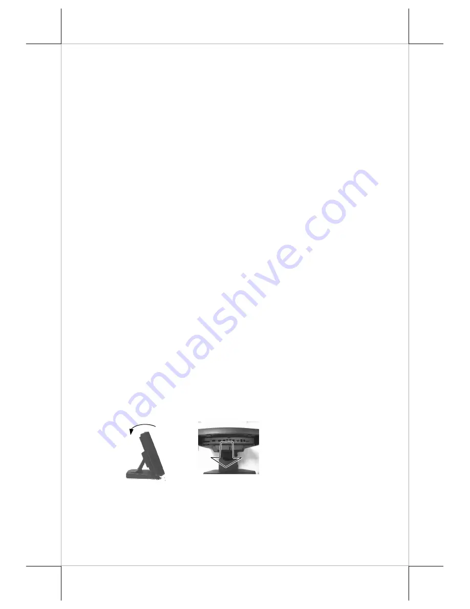


OPENING CABLE COVER 

Please follow steps A to B sequentially with reference to pictures below to 
remove the cable cover for both slim and universal base models. 

Step A:

 Turn panel backward to most horizontal position 

Step B:

 Pull at the removal hollow toward the user 


Step A:

 Push lock/release lever for tilt angle adjust backward 

Step B:

 Turn panel backward to most horizontal position 


B

A


Summary of Contents for KS - 6915

Page 1: ...fits resulting from the furnishing performance or use of this material This information is provided as is and Posiflex Technology Inc expressly disclaims any warranties expressed implied or statutory including without limitation implied warranties of merchantability or fitness for particular purpose good title and against infringement The information in this manual contains only essential hardware...

Page 2: ...dramatically Always fully recharge the UPS battery at least once every 3 months if the battery is not connected Always disconnect the UPS battery from the system if the system is to be left OFF for more than 72 hours to prevent possible damage Only connect the UPS battery back right before you are going to re power on the system Replace the UPS battery as soon as the monitoring software indicates ...

Page 3: ...E foam with extra care and make sure place the terminal and stand on a soft clean flat surface such as table and as show in the picture at the right side Please find the four holes in the top of stand Take the stand and align these four matching holes to the four matching pegs which are in the back on terminal After matching the stand and terminal push the stand to the arrowed direction as show in...

Page 4: ...nt kit such as PD 310 or PD 2604 6 HDD cover 7 Power switch 8 Brightness adjust push button 9 Brightness adjust push button 10 USB ports 11 Base stand 12 Compression lock for base stand cover 13 Cable exit 14 Cable groove 15 Cable exit 16 Cable holder 17 Bottom plate Base Stand and Bottom View Inside touch open door 7 8 9 10 15 16 17 14 18 19 11 12 13 ...

Page 5: ... Gen 6 BASE STAND Front Views Rear Views Side Views PARTS IDENTIFICATION 1 Optional Side mount kit 2 Touch panel LCD panel 3 Power indicator 4 Gen 6 slim base 5 Screw holes for optional rear top mount kit PD 310 or PD 2604 Base Stand and Bottom View 2 3 1 4 5 6 Inside touch open door 7 8 9 10 11 12 13 15 14 ...

Page 6: ... room for optional 2 5 HDD and optional UPS battery in base Also possible to be without base but wall mount bracket for wall mount application f f f f Support WEPOS POS Ready Win7 and Linux environment g g g g High quality 15 17 TFT active matrix LCD panel h h h h LCD panel with easy tilt angle adjustment from 15 to 60 i i i i LCD brightness adjust buttons at side of main unit j j j j Durable resi...

Page 7: ...4GB in one SODIMM r r r r Integrated structure for side mount upgrade kit like SD 400W SD 400T SD 600 SD 800 with software programmable MSR for WEPOS or Win XP pro s s s s Preconditioned power up function by alarm clock or COM port MODEM ring or LAN Option Items Note The underlined items in the following list means that option must be set prior to shipment from the factory The rest items can be se...

Page 8: ...ANEUVERS Some technical maneuvers in KS 6915 6917 7215 7217 series such as serial COM port 5V 12V power supply settings and VGA port 12V power supply setting are supported in system BIOS or Jumper setting Nevertheless such support is limited to the applications of specific Posiflex peripherals and must be disabled when the Posiflex peripherals are disconnected Failure to follow the discipline woul...

Page 9: ...n the cable wire when disconnecting any connector Failure to do this could damage the cable and jack that is considered as an artificial destruction Damages due to incorrect disconnection operation are not covered by product warranty SEPARATING MAIN UNIT In order to settle the touch terminal properly in a point of sale system all the cable connections have to be routed through its base either slim...

Page 10: ...k As for Gen 6 super slim base model please remove the UPS battery bracket on bottom of the stand assembly instead of the bottom plate as in the right picture CABLE PASSAGE FROM BOTTOM FOR Gen 6 SLIM BASE Please route all cables through the cable passage to main unit in desktop mount application Pull the compress lock to open the back cover of base stand Hold them together with a cable tie Pass al...

Page 11: ... battery to UPS battery connector of the main unit only when the system is about to power up for operation Always disconnect the UPS battery when the system is to be left powered off for more than few days Please pay particular attention to the environment requirement for UPS battery in next chapter USING THE TOUCH TERMINAL CABLE PASSAGE FROM BOTTOM FOR Gen 5 UNIVERSAL BASE Place all the cables re...

Page 12: ...2 screws preinstalled Hook the rear bracket of the upgrade kit onto the shoulder screws with the large circular holes Slide to the right of the upgrade kit and gently tighten the shoulder screws Do not overdo the tightening or unrecoverable thread damage will occur Arrange the interface cable to enter the base stand at a notch on the edge near the lock release button as indicated by white arrow in...

Page 13: ...onnectors like the COM3 4 LAN or CR connector have to be gently inserted until a click sound is heard It is recommended that connectors such as the COM1 2 and VGA connector be screwed into place once seated Re adjust the tilt angle of the screen for best viewing Connect the cables to appropriate external devices through the cable exit at the bottom of stand assembly Please make sure that each conn...

Page 14: ...ating system The System Integrator shall take care of software restoration after OS recovered A Posiflex supplied USB interface COMBO drive will be required for such action Other brand CDROM drive may require its own driver different from what supported in the recovery DVD Please use the recovery DVD in rescue operation only Using it otherwise may wipe out whatever stored in the HDD All upgrade de...

Page 15: ...t the battery from the system Reconnect it and turn on the system to recharge the battery for 1 2 hours every 3 months for temperature lower than 30 C Recharge for 1 2 hours every month for temperature over 30 C Temperature above 40 C must be strictly avoided as it could cause termination of battery life and unexpected result even if the battery is not in work The UPS battery can support basically...

Page 16: ...n system is still powered on Please always keep the external power adaptor in a free air circulation POWER ON OFF Touch Open Cover Please refer to the previous chapter PRODUCT PICTURE during this part in order to find out the buttons A gentle tap on the touch open cover at left side of the main unit will open the cover and show the power switch at top area It is preferable to keep this door closed...

Page 17: ...ture please make sure that the software application has the ability to power off the machine In preloaded Windows Posiflex Power Switch Manager in Posiflex Tools in the Program Files helps managing these functions Software Support Features The KS series provides a software power off command for application program maneuvers The KS also provides a specific means for the software to detect if the sy...

Page 18: ...rol buttons please refer to the previous chapter USB PORTS There are in total 6 USB ports for external connection 2 at left side below power switch and LCD brightness adjust buttons 4 in I O area All of them comply with USB 2 0 standard DISPLAY ISSUES Main LCD Display For best viewing result please set your display resolution at 1240 x 1024 for 17 LCD and 1024 x 768 for 15 LCD with high color The ...

Page 19: ... the RAID function is engaged the lower LED marked HDD0 indicates the status of the primary HDD the one in main unit and the upper LED marked HDD1 indicates the secondary HDD the one in base When there is no RAID function the lower LED HDD0 indicates status of either HDD and the upper LED HDD1 indicates the status of optional CF card PARALLEL PORT In KS 6915 6917 7215 7217 system the parallel port...

Page 20: ...siflex USB Touch Manager and a right click sticky button tool in the program group Posiflex USB Touch Tools is installed in the preloaded Windows system with a USB interface touch panel controller This program can also be obtained by download from the POSIFLEX web site RS232 Touch Controller If the KS system purchased is the leading edge Infra Red type touch models the touch controller is RS232 in...

Reviews: