background image


Part 8 

installation of optional UPS battery. 

Note: Never

 press the HDD hold spring carelessly or

 system damages


could 

occur

. The 

user

 shall be 

responsible

 for 

such kind of damage

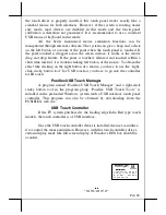
INSTALLING UPS BATTERY (OPTION) 

When the  FT-7715 system is  the optional UPS  model and is ordered 

with  the  UPS  battery,  the  UPS  battery  is  separately  stored  in  the  carton  at 
delivery  while  the  connector  area  inside  back  cover  shows  some  deviation 
from  the  standard  as  in  the  right  picture.  Please 

take  the  battery  out  and  place  it  into  the  battery 
compartment  by  first  pressing  down  the  UPS 
battery  hold  spring  and  then  allow  the  spring  to 

spring back and hold the UPS battery in the compartment as indicated by lower  
rectangle in picture at right. Connect the cable to its connector above the PCI-
E plate window in correct orientation (observe the shape of the  
connector – red wires at left) 

only when the system is about to power up for 

operation

Always disconnect the UPS battery

 when the system is to be left 

powered  off  for  more  than  few  days.  Please  pay  particular  attention  to  the 
environment  requirement  for  UPS  battery  in  the  next  chapter  “USING  THE 
TOUCH TERMINAL”. 

For standard model with SATA HDD RAID function, the UPS battery 

compartment is not available and an external UPS battery must be used instead. 

INSTALLING BASE MOUNT KIT (OPTIONAL) 

When the FT-7715 series is ordered with the base mount upgrade kit 

like  customer  display  PD-2603/2603U,  PD-308/308U or PD-7623  option,  the 
customer display together with the pole for installing them to rear of base will 
be delivered in separate package from  the system  unit. Please follow the step 
by  step  installation  guides  below  with  reference  to  the  attached  pictures.  The 
customer  display  will  occupy  one  USB  or  COM  port  in  the  connection  area. 
Consult your distributor for technical support on setting up the +5V DC supply 
to  the  COM  port  used  if  the  customer  display  is  of  the  serial  interface  type, 
unless  you have a standalone PD peripheral powered  with 12V adaptor itself. 
The  USB  interface  type  such  as  PD-2603U  or  PD-308U  will  be  powered 
through the USB port without specific setting by BIOS. 

1.


First open the back cover of FT system base by pushing in the circled 
buttons on both sides as in the right pictures and lift from bottom edge 

UPS Battery Compartment 

UPS Battery Connector 

Summary of Contents for FT-7715

Page 1: ...ulting from the furnishing performance or use of this material This information is provided as is and Posiflex expressly disclaims any warranties expressed implied or statutory including without limitation implied warranties of merchantability or fitness for particular purpose good title and against infringement The information in this manual contains only essential hardware concerns for general u...

Page 2: ...r maintenance reduces the battery life dramatically Always fully recharge the battery at least once every 3 months if the battery is not connected Always disconnect the UPS battery from the system if the system is to be left OFF for more than 72 hours to prevent possible damage Only connect the UPS battery back right before you are going to re power on the system Replace the battery as soon as the...

Page 3: ...Part 3 INTRODUCTION PRODUCT PICTURES Front Views Rear Views 1 2 12 3 17 Detail inside front cover 6 3 7 2 2 8 10 5 4 4 5 11 9 1 12 16 1 12 15 14 12 12 2 15 13 1 16 12 14 2 Side Views ...

Page 4: ...utton 14 Acoustic vent 15 Back cover release button 16 Reserved back cover lockup screw hole 17 Back cover Please note that the picture for inside front and back cover is for reference only The actual layout may disagree from this picture if there is any difference in model or options selected or in the system revision Please follow the actual layout for cable connections in this case CAUTION DO N...

Page 5: ... Core i3 2330E 2 2G 3M Cache CPU Intel Core i5 2510E 2 5G 3M Cache CPU b b b b Fan free structure with Aluminum die cast main unit base casing for harsh environment or metal c c c c Data storage device One 2 5 SATA HDD or SSD kit optional and status indicator in base or CFast card optionally for optional UPS model only 1 HDD is available for RAID function support RAID 1 disk mirroring for 2nd 2 5 ...

Page 6: ... memory size shared from system memory p p p p Support high performance DDR3 SDRAM with maximum memory size 8GB in 2 modules q q q q Integrated structure for side mount upgrade kit like FA 200 with software programmable MSR parameters for Win XP Pro or Win 7 r r r r Built in internal stereo speaker with 2W audio amplifier s s s s Preconditioned power up function by alarm clock Option Items Note Th...

Page 7: ...TIONS When the FT 7715 system is ordered with options like expanded system memory or side mount upgrade kit the option s is are already installed in the system delivered Therefore no more installation is required HALF LENGTH PCI E EXTENSION CARD Adding a half length PCI E extension card is possible However the whole operation will involve cautiously accessing the interior of the system replacing t...

Page 8: ...the environment requirement for UPS battery in the next chapter USING THE TOUCH TERMINAL For standard model with SATA HDD RAID function the UPS battery compartment is not available and an external UPS battery must be used instead INSTALLING BASE MOUNT KIT OPTIONAL When the FT 7715 series is ordered with the base mount upgrade kit like customer display PD 2603 2603U PD 308 308U or PD 7623 option th...

Page 9: ...only or both options the connection to the FT 7715 system is through an internal cable in the right side cover of the LCD touch unit Remove the 2 circled screws in the left picture to remove the cover for side mount upgrade kit Take out the cable inside this cover as circled in the left picture here and connect it to connector inside the side mount upgrade kit as arrowed in the same picture Gently...

Page 10: ... the connector marked CR found in the main connection area in the system Each 8 pole plug should be inserted into the connector marked signal cable from POS Printer at the rear of one of the cash drawers The cable lengths for the two 8 pole plugs are different Use the shorter one for the original cash drawer CR1 and use the longer one for the extended cash drawer CR2 that will be distinguished by ...

Page 11: ... are available in the subfolder drivers in OS recovered HDD and the latest versions of these required drivers will be available on our web http www posiflex com tw Then follow instructions from your system integrator for software recovery OPERATING SYSTEM INSTALLATION This product is a highly professionalized equipment The installation of an OS into a machine without any preloaded OS could constit...

Page 12: ...ote that if the FT system is improperly turned off before a complete boot up procedure the above preset power on control functions will be disabled until next turning off after a complete boot up To enable Wake System with Fixed Dynamic Time 1 Press Del on system startup to access BIOS setup 2 On Advanced tab at Wake system with Fixed time or Wake system with Dynamic time select Enabled and set a ...

Page 13: ...er than 30 C Recharge for 1 2 hours every month for temperature over 30 C Temperature above 40 C must be strictly avoided as it could cause termination of battery life and unexpected result even if the battery is not in work The UPS battery can support basically the data preservation and smooth running of the system during intermittent or few minutes within 30 min depending on loading and battery ...

Page 14: ...eration The power cable the power outlet and any power fusing arrangements must conform to local safety regulations Please never do any connection disconnection when system is still powered on Please always keep the system in a free air circulation POWER ON OFF Power Indicator The power indicator is the backlight LED module under the logo that serves for several purposes The relationship between t...

Page 15: ...d on the system just remains on and unaffected When using this feature please make sure that the software application has the ability to power off the machine In preloaded Windows Posiflex Power Switch Manager in Posiflex Tools in the Program Files helps managing these functions There must always be at least 10 seconds waiting before switching on again once the system is powered off successfully S...

Page 16: ...the right left button makes the LCD display brighter dimmer by a minute amount A holding touch makes continuous change till release Main LCD Display For best viewing result please set your display resolution at 1024 x 768 with high color for FT 7715 In configuration of 4GB system memory installed max 1 7 GB can be shared as the video memory under the preloaded 64 bit operating system condition VGA...

Page 17: ...LCD brightness adjustment buttons indicates the operation status of the HDD The LED nearest to the front cover indicates the LAN status When it lights up in green the onboard LAN chip is linked When it flashes in yellow data transmission in LAN is in process The LAN status indication is also observable on the LAN connector in back cover area SERIAL PORTS COM1 2 3 4 5 6 In FT system there are 6 sta...

Page 18: ...effect like clicking on the right button of a mouse you have to use the right click sticky button tool for USB touch or you have to go into the controller for IR touch Posiflex USB Touch Manager A program named Posiflex USB Touch Manager and a right click sticky button tool in the program group Posiflex USB Touch Tools is installed in the preloaded Windows system with a USB interface touch panel c...

Reviews: