Part 17
Display Utility Driver
The end user of the FT-7715 terminals is not supposed to install the
utility drivers personally. If an optional preloaded OS is ordered, the required
driver will be already installed in the preloaded OS. However, the driver will
always be available over our web site: http://www.posiflex.com
FRONT COVER & OTHER INDICATORS
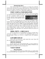
At left part on the front side of base unit, there is a front cover. Pick it
up at the bottom notch and the CFast memory card reader slot and a USB port
for user’s convenience will be accessible.
To place the front cover back please insert
first the top edge and then push the bottom
edge in.
In the area between the front cover and the LCD brightness adjust
buttons, there are several LED indicators for status other than the power status
which is done by the LED module under logo in bottom center of the LCD
panel. The upper one of the 2 LED’s near the LCD brightness adjustment
buttons indicates the operation status of the HDD.The LED nearest to the front
cover indicates the LAN status. When it lights up in green, the onboard LAN
chip is linked. When it flashes in yellow, data transmission in LAN is in
process. The LAN status indication is also observable on the LAN connector in
back cover area.
SERIAL PORTS – COM1/2/3/4/5/6
In FT system, there are 6 standard RS232 serial ports available. These
serial ports can supply +5 V or +12V DC after proper BIOS setup (for +5V
DC) and jumper settings (for +12V DC) to support Posiflex POS peripheral
devices.
CUSTOMER DISPLAY
Please follow the instructions on the manual that comes along with
the customer display when it is installed.
SERVICE WINDOW
On the connector area of the main unit, there is a service window for
more technical settings. Please note that only those qualified technicians may
adjust in the service window but not for average user.
TOUCH FUNTION
Mouse Emulation
The touch panel in FT system uses USB interface as standard. Only
the optional InfraRed type touch panel of FT-7715 uses USB interface. When


