COM Express
™
PORTWELL PCOM-B700G User's Guide
Copyright © PORTWELL 2018 PCOM-B700G User's Guide
136
Platform Thermal Configuration
Page 1: ...COM Express PORTWELL PCOM B700G User s Guide Copyright PORTWELL 2018 PCOM B700G User s Guide 1 COM Express PCOM B700G User s Guide R1 2 ...
Page 2: ...ORTWELL PCOM B700G User s Guide Copyright PORTWELL 2018 PCOM B700G User s Guide 2 Revision History Rev Note Date R1 0 Preliminary March 2018 R1 1 Update mechanical drawing June 2018 R1 2 Update BIOS Screen June 2018 ...
Page 3: ...5 Mechanical Dimensions 21 3 6 3 SODIMM socket design 25 3 7 Environmental Specifications 25 3 8 Ordering Guide 25 4 Heat sink Cooler 27 4 1 H S Assembly guide 28 4 2 Packaging 28 5 Signal Descriptions and Pin out Tables 29 6 BIOS Setup Items 69 6 1 Entering Setup Launch System Setup 70 6 2 Main 71 6 3 Advanced 72 Trusted Computing 73 ACPI Settings 74 ISIO Super IO Configuration 75 Serial Port 1 2...
Page 4: ...Configuration 87 Info Report Configuration 88 USB Configuration 89 6 4 IntelRCSetup 90 Processor Configuration 91 Advanced Power Management Configuration 92 CPU P State Control 93 XE Ratio Limit 94 CPU C State Control 95 CPU T State Control 96 CPU Thermal Management 97 CPU Advanced PM Turning 98 Energy Perf BIAS 99 Program PowerCTL_MSR 100 Program PPO_CURT_CFG_CTRL_MSR 101 PSI CONFIG 102 Program C...
Page 5: ...Thermal 115 Memory Power Savings Advanced Options 116 Memory Timings Voltage Override 117 Memory Map 118 Memory RAS Configuration 119 IIO Configuration 120 IIO 0 3 Configuration 121 IOAT Configuration 122 IIO General Configuration 123 Intel VT for Directed I O VT d 124 IIO South Complex Configuration 125 PCH Configuration 126 PCH Devices 127 PCI Express Configuration 128 PCI Express Root Port 1 8 ...
Page 6: ...guration 141 Server ME Configuration 142 Runtime Error Logging 143 Whea Settings 144 Memory Error Enabling 145 IIO Error Enable 146 IIO Coherency Interface Error Enable 147 PCI PCI Error Enabling 148 Reserve Memory 149 6 5 Security 150 6 6 Boot 151 UEFI USB key Drive BBS Priorities 152 6 7 Event Logs 153 Change Smbios Event Log Settings 154 View Smbios Event Log 155 6 8 Save Exit 156 7 System Reso...
Page 7: ...rocessor list 16 Table 3 Supported OS list 17 Table 4 Windows OS driver list 18 Table 5 Electrical characteristics 19 Table 6 Weight 24 Table 7 Environmental Specifications 25 Table 8 Ordering Guide PCOM B700G 26 Table 9 Ordering Guide Accessory 26 Table 10 Signal Tables Terminology Descriptions 29 Table 11 Pin out description 68 Table 12 System Resources 157 ...
Page 8: ... Figures Figure 1 Block Diagram 12 Figure 2 Power on sequence 20 Figure 4 Mechanical Dimensions Top 21 Figure 5 Mechanical Dimensions Bottom 22 Figure 6 Mechanical Dimensions Assembly view 23 Figure 8 Heat sink cooler mechanical dimensions 27 Please refer Figure 6 Mechanical Dimensions Assembly view 28 ...
Page 9: ...s or corruption of data or any other special incidental or consequential damages caused by the use or misuse of or inability to use the PORTWELL products regardless of the legal theory on which the claim is based and even if PORTWELL has been advised of the possibility of such damages The information contained within this user manual including but not limited to any other product specification POR...
Page 10: ...r our customers so that our products can be easily used and implemented We request that you first visit our website at http www PORTWELL com tw support for the latest documentation utilities and drivers which have been made available to assist you If you still require assistance after visiting our website you can contact our technical support department by email at tsd mail PORTWELL com tw for fur...
Page 11: ...applications that do not require graphics support Specifically the COM Express 3 0 specification s Type 7 pinout when compared to the Type 6 pinout trades all the graphics interfaces for up to four 10GbE ports and a total of 32 PCIe lanes This makes it ideal for applications in micro server and the like that require low power consumption while supporting high computing performance and communicatio...
Page 12: ...COM Express PORTWELL PCOM B700G User s Guide Copyright PORTWELL 2018 PCOM B700G User s Guide 12 2 Block Diagram Figure 1 Block Diagram ...
Page 13: ...ecifications Table 1 PCOM B700GVG SPEC Note1 The PEG available lanes configurations are shown below 1x16 Default 0 1 2 3 4 5 6 7 8 9 10 11 12 13 14 15 0 1 2 3 4 5 6 7 0 1 2 3 4 5 6 7 0 1 2 3 0 1 2 3 0 1 2 3 0 1 2 3 0 1 2 3 4 5 6 7 0 1 2 3 0 1 2 3 0 1 2 3 0 1 2 3 4 5 6 7 0 1 2 3 2x8 4x4 1x8 2x4 2x4 1x8 ...
Page 14: ... 8 8 8 16 16 16 24 32 Processor Base Frequency 1 20 GHz 2 20 GHz 1 60 GHz 1 50 GHz 2 20 GHz 1 70 GHz 1 60 GHz 2 00 GHz 1 50 GHz 1 30 GHz Max Turbo Frequency 1 20 GHz 2 60 GHz 2 20 GHz 2 10 GHz 2 70 GHz 2 30 GHz 2 20 GHz 2 60 GHz 2 10 GHz 2 10 GHz Cache 3 MB 3 MB 6 MB 6 MB 6 MB 12 MB 12 MB 12 MB 18 MB 24 MB TDP 20 W 25 W 25 W 25 W 35 W 35 W 35 W 45 W 45 W 45 W ECC Memory Supported Yes Yes Yes Yes Y...
Page 15: ...s Yes Yes Yes Yes Yes Yes Yes Yes Intel Virtualization Technology VT x Yes Yes Yes Yes Yes Yes Yes Yes Yes Yes Intel Virtualization Technology for Directed I O VT d Yes Yes Yes Yes Yes Yes Yes Yes Yes Yes Intel VT x with Extended Page Tables EPT Yes Yes Yes Yes Yes Yes Yes Yes Yes Yes Intel TSX NI Yes Yes Yes Yes Yes Yes Yes Yes Yes Yes Intel 64 Yes Yes Yes Yes Yes Yes Yes Yes Yes Yes Instruction ...
Page 16: ...Yes Yes Yes Thermal Monitoring Technologies Yes Yes Yes Yes Yes Yes Yes Yes Yes Yes Intel AES New Instructions Yes Yes Yes Yes Yes Yes Yes Yes Yes Yes Secure Key Yes Yes Yes Yes Yes Yes Yes Yes Yes Yes Trusted Execution Technology Yes Yes Yes Yes Yes Yes Yes Yes Yes Yes Execute Disable Bit Yes Yes Yes Yes Yes Yes Yes Yes Yes Yes OS Guard Yes Yes Yes Yes Yes Yes Yes Yes Yes Yes Table 2 PCOM B700G P...
Page 17: ...he following operating systems Vendor Operating System Supported Microsoft Windows 7 32 64bit YES Windows 8 32 64bit YES Windows 8 1 32 64bit YES Windows 10 32 64bit YES Microsoft Windows 2008 R2 SP1 YES Microsoft Windows 2012 YES Microsoft Windows 2012 R2 YES Linux Fedora 22 kernel 4 0 4 301 YES Ubuntu 15 04 kernel 3 11 6 4 YES Table 3 Supported OS list ...
Page 18: ...64bit Microsoft Windows 8 32 64bit Microsoft Windows 8 1 32 64bit Graphics_Win7_32_64 Microsoft Windows 7 32 64bit Graphics_Win8_81_32_64 Microsoft Windows 8 8 1 32 64bit Graphic_Windows10_Driver Microsoft Windows 10 32 64bit I210LAN_Win7_8_81_32_64 Microsoft Windows 7 32 64bit Microsoft Windows 8 8 1 32 64bit Windows Server 2008 R2 Microsoft Windows 2012 Microsoft Windows 2012 R2 XHCI_Win7_32_64 ...
Page 19: ... s Guide Copyright PORTWELL 2018 PCOM B700G User s Guide 19 3 4 Electrical Characteristics Input voltage 12VDC Nominal 6VDC 19VDC Wide range RTC Battery Power on mode AT Mode Table 5 Electrical characteristics PCOM B700GVG Power sequence ...
Page 20: ...COM Express PORTWELL PCOM B700G User s Guide Copyright PORTWELL 2018 PCOM B700G User s Guide 20 Figure 2 Power on sequence ...
Page 21: ...COM Express PORTWELL PCOM B700G User s Guide Copyright PORTWELL 2018 PCOM B700G User s Guide 21 3 5 Mechanical Dimensions Figure 3 Mechanical Dimensions Top ...
Page 22: ...COM Express PORTWELL PCOM B700G User s Guide Copyright PORTWELL 2018 PCOM B700G User s Guide 22 Figure 4 Mechanical Dimensions Bottom ...
Page 23: ...COM Express PORTWELL PCOM B700G User s Guide Copyright PORTWELL 2018 PCOM B700G User s Guide 23 Figure 5 Mechanical Dimensions Assembly view ...
Page 24: ...COM Express PORTWELL PCOM B700G User s Guide Copyright PORTWELL 2018 PCOM B700G User s Guide 24 Net weight Module 0g 2 Cooler H S FAN 0g 2 Table 6 Weight ...
Page 25: ...nd note that there are 2 SODIMM socket of channel 0 the CH0 SODIMM1 the bottom one works only if CH0 SDDIMM0 the top one is inserted 3 7 Environmental Specifications Storage Temperature 20 C 85 C Operation Temperature 0 C 60 C Extended 40 C 85 C Processor dependent Storage Humidity 0 95 Operation Humidity 0 95 Table 7 Environmental Specifications 3 8 Ordering Guide PCOM B700GVG Product Ordering P ...
Page 26: ...0G D1548 AB1 3F53 Available PCOM B700G D1559 AB1 3G82 Available Wide Temp PCOM B700G D1577 AB1 3G83 Available Table 8 Ordering Guide PCOM B700G Accessory Accessory Ordering P N Status PCOM B700G Cooler B9971570 Available Evaluation Carrier PCOM C700 AB1 3F19Z Available Table 9 Ordering Guide Accessory PCOM C700 PCOM B700GVG Evaluation carrier EVA Board PCOM C700 is designed for functions verificat...
Page 27: ...COM Express PORTWELL PCOM B700G User s Guide Copyright PORTWELL 2018 PCOM B700G User s Guide 27 4 Heat sink Cooler Heat sink Dimensions Figure 6 Heat sink cooler mechanical dimensions ...
Page 28: ...L 2018 PCOM B700G User s Guide 28 4 1 H S Assembly guide Please refer Figure 7 Mechanical Dimensions Assembly view 4 2 Packaging Package Appearance Size Anti Static bubble bag 180x135mm White Paper Box 210x151x40mm Shipping Box 10 pcs White paper box 595x300x195mm ...
Page 29: ... DC coupled on the COM Express Module and shall be assumed to be AC coupled off Module close to the signal source If the target PCI Express device resides on the Carrier Board the Module PCIE receive lanes target PCIE device transmit lanes shall be AC coupled near the device on the Carrier Board If the Carrier Board implements a PCIE slot then these signals shall be AC coupled on the add in card n...
Page 30: ...E0_LINK100 Gigabit Ethernet Controller 0 100 Mbit sec link indicator active low OD CMOS 3 3V Suspend 3 3V A5 GBE0_LINK1000 Gigabit Ethernet Controller 0 1000 Mbit sec link indicator active low OD CMOS 3 3V Suspend 3 3V A6 GBE0_MDI2 Gigabit Ethernet Controller 0 Media Dependent Interface Differential Pairs I O Analog 3 3V max Suspend A7 GBE0_MDI2 Gigabit Ethernet Controller 0 Media Dependent Interf...
Page 31: ...Carrier Board Ethernet channel 0 magnetics center tap GND min 3 3V max Placeholder 0 ohm to V_1P5_L1 A15 SUS_S3 Indicates system is in Suspend to RAM state Active low output An inverted copy of SUS_S3 on the Carrier Board may be used to enable the non standby power on a typical ATX supply O CMOS 3 3V Suspend 3 3V PD 10kohm A16 SATA0_TX Serial ATA or SAS Channel 0 transmit differential pair O SATA ...
Page 32: ...state O CMOS 3 3V Suspend 3 3V There is no SUS_S5 in Broadwell DE A25 PCIE_TX14 PCI Express Differential Transmit Pairs O PCIE AC coupled on Module A26 PCIE_TX14 PCI Express Differential Transmit Pairs O PCIE AC coupled on Module A27 BATLOW Indicates that external battery is low This port provides a battery low signal to the Module for orderly transitioning to power saving or power cut off ACPI mo...
Page 33: ...36 PCIE_TX13 PCI Express Differential Transmit Pairs O PCIE AC coupled on Module A37 PCIE_TX13 PCI Express Differential Transmit Pairs O PCIE AC coupled on Module A38 GND GND A39 PCIE_TX12 PCI Express Differential Transmit Pairs O PCIE AC coupled on Module A40 PCIE_TX12 PCI Express Differential Transmit Pairs O PCIE AC coupled on Module A41 GND FIXED GND FIXED A42 USB2 USB differential pairs chann...
Page 34: ...ls 0 All USB ports except USB7 if implemented shall be host ports I O USB 3 3V Suspend 3 3V A47 VCC_RTC Real time clock circuit power input Nominally 3 0V PWR A48 RSVD Reserved Pin A49 GBE0_SDP Gigabit Ethernet Controller 0 Software Definable Pins Can also be used for IEEE1588 support such as a 1pps signal See section 4 3 4 for details I O CMOS 3 3V Suspend 3 3V PU 10K ohm to 3VSB A50 LPC_SERIRQ E...
Page 35: ...ss Differential Transmit Pairs O PCIE AC coupled on Module A59 PCIE_TX3 PCI Express Differential Transmit Pairs O PCIE AC coupled on Module A60 GND FIXED GND FIXED A61 PCIE_TX2 PCI Express Differential Transmit Pairs O PCIE AC coupled on Module A62 PCIE_TX2 PCI Express Differential Transmit Pairs O PCIE AC coupled on Module A63 GPI1 General purpose input pins Pulled high internally on the Module I...
Page 36: ...CIE AC coupled on Module A72 PCIE_TX8 PCI Express Differential Transmit Pairs O PCIE AC coupled on Module A73 GND GND A74 PCIE_TX9 PCI Express Differential Transmit Pairs O PCIE AC coupled on Module A75 PCIE_TX9 PCI Express Differential Transmit Pairs O PCIE AC coupled on Module A76 GND GND A77 PCIE_TX10 PCI Express Differential Transmit Pairs O PCIE AC coupled on Module A78 PCIE_TX10 PCI Express ...
Page 37: ...d Pin A88 PCIE_CLK_REF Reference clock output for all PCI Express and PCI Express Graphics lanes O PCIE PCIE A89 PCIE_CLK_REF Reference clock output for all PCI Express and PCI Express Graphics lanes O PCIE PCIE A90 GND FIXED GND FIXED A91 SPI_POWER Power supply for Carrier Board SPI sourced from Module nominally 3 3V The Module shall provide a minimum of 100mA on SPI_POWER Carriers shall use less...
Page 38: ... has an internal pull down This signal is used to indicate Physical Presence to the TPM I CMOS 3 3V 3 3V A97 TYPE10 Dual use pin Indicates to the Carrier Board that a Type 10 module is installed Indicates to the Carrier that a Rev 1 0 2 0 module is installed A98 SER0_TX General purpose serial port transmitter O CMOS 5V 12V Placeholder PD 4 7K A99 SER0_RX General purpose serial port receiver I CMOS...
Page 39: ... 12V nominal PWR 12V A107 VCC_12V Primary power input 12V nominal PWR 12V A108 VCC_12V Primary power input 12V nominal PWR 12V A109 VCC_12V Primary power input 12V nominal PWR 12V A110 GND FIXED GND FIXED B1 GND FIXED GND FIXED B2 GBE0_ACT Gigabit Ethernet Controller 1 activity indicator active low OD CMOS 3 3V Suspend 3 3V B3 LPC_FRAME ESPI_CS0 LPC frame indicates the start of an LPC cycle Shared...
Page 40: ..._DRQ0 ESPI_ALERT0 LPC serial DMA request Shared pin with ESPI_ALERT I CMOS 3 3V 3 3V B9 LPC_DRQ1 ESPI_ALERT1 LPC serial DMA request Shared pin with ESPI_ALERT I CMOS 3 3V 3 3V B10 LPC_CLK ESPI_CK LPC clock output 33MHz nominal Shared pin with ESPI_Clock O CMOS 3 3V 3 3V B11 GND FIXED GND FIXED B12 PWRBTN Power button to bring system out of S5 soft off active on falling edge I CMOS 3 3V Suspend 3 3...
Page 41: ...I_RESET Indicates imminent suspend operation used to notify LPC devices Shared pin with ESPI_RESET O CMOS 3 3V Suspend 3 3V B19 SATA1_RX Serial ATA or SAS Channel 1 receive differential pair I SATA AC coupled on Module B20 SATA1_RX Serial ATA or SAS Channel 1 receive differential pair I SATA AC coupled on Module B21 GND FIXED GND FIXED B22 PCIE_RX15 PCI Express Differential Receive Pairs I PCIE AC...
Page 42: ... Reserved Pin B29 RSVD Reserved Pin B30 RSVD Reserved Pin B31 GND FIXED GND FIXED B32 SPKR Output for audio enunciator O CMOS 3 3V 3 3V B33 I2C_CK General purpose I2C port clock output I O CMOS 3 3V Suspend 3 3V PU 2 2k ohm to 3 3V B34 I2C_DAT General purpose I2C port data I O line I O CMOS 3 3V Suspend 3 3V PU 2 2k ohm to 3 3V B35 THRM Input from off Module temp sensor indicating an over temp sit...
Page 43: ... 3V Suspend 3 3V B43 USB3 USB differential pairs channels 3 All USB ports except USB7 if implemented shall be host ports I O USB 3 3V Suspend 3 3V B44 USB_0_1_OC USB over current sense USB channels 0 and 1 A pull up for this line shallbe present on the Module Do not pull this line high on the Carrier Board I CMOS 3 3V Suspend 3 3V PU 10 kohm to 3VSB B45 USB1 USB differential pairs channels 1 All U...
Page 44: ...ed up on the Module This signal is a don t care for Modules that do not support eSPI I CMOS NA B48 USB0_HOST_PRSNT Module USB client may may detect the presence of a USB host on USB0 A high value indicates that a host is present I CMOS 3 3V Suspend 3 3V B49 SYS_RESET Reset button input Active low request for module to reset and reboot May be falling edge sensitive For situations when SYS_RESET is ...
Page 45: ...ss Differential Receive Pairs I PCIE AC coupled off Module B53 PCIE_RX5 PCI Express Differential Receive Pairs I PCIE AC coupled off Module B54 GPO1 General purpose output pins Upon a hardware reset these outputs should be low O CMOS 3 3V 3 3V B55 PCIE_RX4 PCI Express Differential Receive Pairs I PCIE AC coupled off Module B56 PCIE_RX4 PCI Express Differential Receive Pairs I PCIE AC coupled off M...
Page 46: ...tial Receive Pairs I PCIE AC coupled off Module B65 PCIE_RX1 PCI Express Differential Receive Pairs I PCIE AC coupled off Module B66 WAKE0 PCI Express wake up signal I CMOS 3 3V Suspend 3 3V PU 1k ohm to 3VSB B67 WAKE1 General purpose wake up signal Maybe used to implement wake up on PS2 keyboard or mouse activity I CMOS 3 3V Suspend 3 3V PU 10k ohm to 3VSB B68 PCIE_RX0 PCI Express Differential Re...
Page 47: ...xpress Differential Receive Pairs I PCIE AC coupled off Module B78 PCIE_RX10 PCI Express Differential Receive Pairs I PCIE AC coupled off Module B79 GND GND B80 GND FIXED GND FIXED B81 PCIE_RX11 PCI Express Differential Receive Pairs I PCIE AC coupled off Module B82 PCIE_RX11 PCI Express Differential Receive Pairs I PCIE AC coupled off Module B83 GND GND B84 VCC_5V_SBY Standby power input 5 0V nom...
Page 48: ...er when NC SI is not used on Carrier I 3 3V Suspend 3 3V B92 NCSI_RXD1 NC SI Receive Data from NC to BMC O 3 3V Suspend 3 3V PU 5 1K to 1 05V B93 NCSI_RXD0 NC SI Receive Data from NC to BMC O 3 3V Suspend 3 3V PU 5 1K to 1 05V B94 NCSI_CRS_DV NC SI Carrier Sense Receive Data Valid to MC indicating that the transmitted data from NC to BMC is valid O 3 3V Suspend 3 3V PD 270 ohm B95 NCSI_TXD1 NC SI ...
Page 49: ... the Pulse Width Modulation PWM technique to control the fan s RPM O CMOS 3 3V 12V PU 10K to 3 3V B102 FAN_TACHIN Fan tachometer input for a fan with a two pulse output I CMOS 3 3V 12V PU 10K to 3 3V B103 SLEEP Sleep button Low active signal used by the ACPI operating system to bring the system to sleep state or to wake it up again I CMOS 3 3V Suspend 12V PU 10K to 3VSB B104 VCC_12V Primary power ...
Page 50: ...irs for the SuperSpeed USB data path I PCIE AC coupled off Module C5 GND GND C6 USB_SSRX1 Additional transmit signal differential pairs for the SuperSpeed USB data path I PCIE AC coupled off Module C7 USB_SSRX1 Additional transmit signal differential pairs for the SuperSpeed USB data path I PCIE AC coupled off Module C8 GND GND C9 USB_SSRX2 Additional transmit signal differential pairs for the Sup...
Page 51: ...rs between the MAC and an external PHY O 3 3V Suspend 3 3V I2C Mode I2C clock signal of the 2 wire management interface used for serial data transfers between the MAC and an external PHY I O OD 3 3V Suspend 3 3V C16 10G_PHY_MDC_SCL2 MDIO Mode Management Data I O interface mode clock signal for serial data transfers between the MAC and an external PHY O 3 3V Suspend 3 3V I2C Mode I2C clock signal o...
Page 52: ...upt pin from copper PHY or optical SFP Module to the 10GbE controller I 3 3V Suspend 3 3V C25 GND GND C26 10G_KR_RX3 10GBASE KR ports receive input differential pairs I KR AC coupled on Module C27 10G_KR_RX3 10GBASE KR ports receive input differential pairs I KR AC coupled on Module C28 GND GND C29 10G_KR_RX2 10GBASE KR ports receive input differential pairs I KR AC coupled on Module C30 10G_KR_RX...
Page 53: ...Suspend 3 3V C35 10G_PHY_RST_01 Output signal that resets an optical PHY on port 0 and port1 Not used with copper PHY O 3 3V Suspend 3 3V C36 10G_LED_SDA I2C Data of the 2 wire interface that transfers LED signals and PHY straps for I2C or MDIO operation of optical PHYs I O OD 3 3V Suspend 3 3V C37 10G_LED_SCL I2C Clock of the 2 wire interface that transfers LED and strap signals for I2C or MDIO o...
Page 54: ...O 3 3V Suspend 3 3V PU 1K to 3VSB C41 GND FIXED GND FIXED C42 10G_KR_RX1 10GBASE KR ports receive input differential pairs I KR AC coupled on Module C43 10G_KR_RX1 10GBASE KR ports receive input differential pairs I KR AC coupled on Module C44 GND GND C45 10G_PHY_MDC_SCL1 MDIO Mode Management Data I O interface mode clock signal for serial data transfers between the MAC and an external PHY O 3 3V ...
Page 55: ...3 3V C48 GND GND C49 10G_KR_RX0 10GBASE KR ports receive input differential pairs I KR AC coupled on Module C50 10G_KR_RX0 10GBASE KR ports receive input differential pairs I KR AC coupled on Module C51 GND FIXED GND FIXED C52 PCIE_RX16 PCI Express Differential Receive Pairs I PCIE AC coupled off Module C53 PCIE_RX16 PCI Express Differential Receive Pairs I PCIE AC coupled off Module C54 TYPE0 The...
Page 56: ...ial Receive Pairs I PCIE AC coupled off Module C62 PCIE_RX19 PCI Express Differential Receive Pairs I PCIE AC coupled off Module C63 RSVD Reserved Pin C64 RSVD Reserved Pin C65 PCIE_RX20 PCI Express Differential Receive Pairs I PCIE AC coupled off Module C66 PCIE_RX20 PCI Express Differential Receive Pairs I PCIE AC coupled off Module C67 RAPID_SHUTDOWN Trigger for Rapid Shutdown Must be driven to...
Page 57: ...ive Pairs I PCIE AC coupled off Module C76 GND GND C77 RSVD Reserved Pin C78 PCIE_RX24 PCI Express Differential Receive Pairs I PCIE AC coupled off Module C79 PCIE_RX24 PCI Express Differential Receive Pairs I PCIE AC coupled off Module C80 GND FIXED GND FIXED C81 PCIE_RX25 PCI Express Differential Receive Pairs I PCIE AC coupled off Module C82 PCIE_RX25 PCI Express Differential Receive Pairs I PC...
Page 58: ...eceive Pairs I PCIE AC coupled off Module C93 GND GND C94 PCIE_RX29 PCI Express Differential Receive Pairs I PCIE AC coupled off Module C95 PCIE_RX29 PCI Express Differential Receive Pairs I PCIE AC coupled off Module C96 GND GND C97 RSVD Reserved Pin C98 PCIE_RX30 PCI Express Differential Receive Pairs I PCIE AC coupled off Module C99 PCIE_RX30 PCI Express Differential Receive Pairs I PCIE AC cou...
Page 59: ...Primary power input 12V nominal PWR 12V C109 VCC_12V Primary power input 12V nominal PWR 12V C110 GND FIXED GND FIXED D1 GND FIXED GND FIXED D2 GND GND D3 USB_SSTX0 Additional transmit signal differential pairs for the SuperSpeed USB data path O PCIE AC coupled on Module D4 USB_SSTX0 Additional transmit signal differential pairs for the SuperSpeed USB data path O PCIE AC coupled on Module D5 GND G...
Page 60: ...B data path O PCIE AC coupled on Module D11 GND FIXED GND FIXED D12 USB_SSTX3 Additional transmit signal differential pairs for the SuperSpeed USB data path O PCIE AC coupled on Module D13 USB_SSTX3 Additional transmit signal differential pairs for the SuperSpeed USB data path O PCIE AC coupled on Module D14 GND GND D15 10G_PHY_MDIO_SDA3 MDIO Mode Management Data I O interface mode data signal for...
Page 61: ...also be used for IEEE1588 support such as a 1pps signal I O 3 3V Suspend 3 3V D18 GND GND D19 PCIE_TX6 PCI Express Differential Transmit Pairs O PCIE AC coupled on Module D20 PCIE_TX6 PCI Express Differential Transmit Pairs O PCIE AC coupled on Module D21 GND FIXED GND FIXED D22 PCIE_TX7 PCI Express Differential Transmit Pairs O PCIE AC coupled on Module D23 PCIE_TX7 PCI Express Differential Trans...
Page 62: ...SCL3 I2C clock signal of the 2 wire management interface used by the 10GbE controller to access the management registers of an external Optical SFP Module I O OD 3 3V Suspend 3 3V D33 10G_SFP_SCL2 I2C clock signal of the 2 wire management interface used by the 10GbE controller to access the management registers of an external Optical SFP Module I O OD 3 3V Suspend 3 3V D34 10G_PHY_SEL_23 Phy mode ...
Page 63: ...ntroller to access the management registers of an external Optical SFP Module I O OD 3 3V Suspend 3 3V PU 4 7K to 3VSB D39 10G_SFP_SCL0 I2C clock signal of the 2 wire management interface used by the 10GbE controller to access the management registers of an external Optical SFP Module I O OD 3 3V Suspend 3 3V PU 4 7K to 3VSB D40 10G_SDP1 Software Definable Pins Can also be used for IEEE1588 suppor...
Page 64: ... O interface mode data signal for serial data transfers between the MAC and an external PHY O 3 3V Suspend 3 3V I2C Mode I2C data signal of the 2 wire management interface used for serial data transfers between the MAC and an external PHY I O OD 3 3V Suspend 3 3V D47 10G_INT1 Interrupt pin from copper PHY or optical SFP Module to the 10GbE controller I 3 3V Suspend 3 3V D48 GND GND D49 10G_KR_TX0 ...
Page 65: ...the Pin out Type that is implemented on the Module Connect to GND D58 PCIE_TX18 PCI Express Differential Transmit Pairs O PCIE AC coupled on Module D59 PCIE_TX18 PCI Express Differential Transmit Pairs O PCIE AC coupled on Module D60 GND FIXED GND FIXED D61 PCIE_TX19 PCI Express Differential Transmit Pairs O PCIE AC coupled on Module D62 PCIE_TX19 PCI Express Differential Transmit Pairs O PCIE AC ...
Page 66: ...smit Pairs O PCIE AC coupled on Module D73 GND GND D74 PCIE_TX23 PCI Express Differential Transmit Pairs O PCIE AC coupled on Module D75 PCIE_TX23 PCI Express Differential Transmit Pairs O PCIE AC coupled on Module D76 GND GND D77 RSVD Reserved Pin D78 PCIE_TX24 PCI Express Differential Transmit Pairs O PCIE AC coupled on Module D79 PCIE_TX24 PCI Express Differential Transmit Pairs O PCIE AC coupl...
Page 67: ...irs O PCIE AC coupled on Module D90 GND FIXED GND FIXED D91 PCIE_TX28 PCI Express Differential Transmit Pairs O PCIE AC coupled on Module D92 PCIE_TX28 PCI Express Differential Transmit Pairs O PCIE AC coupled on Module D93 GND GND D94 PCIE_TX29 PCI Express Differential Transmit Pairs O PCIE AC coupled on Module D95 PCIE_TX29 PCI Express Differential Transmit Pairs O PCIE AC coupled on Module D96 ...
Page 68: ...nsmit Pairs O PCIE AC coupled on Module D103 GND GND D104 VCC_12V Primary power input 12V nominal PWR 12V D105 VCC_12V Primary power input 12V nominal PWR 12V D106 VCC_12V Primary power input 12V nominal PWR 12V D107 VCC_12V Primary power input 12V nominal PWR 12V D108 VCC_12V Primary power input 12V nominal PWR 12V D109 VCC_12V Primary power input 12V nominal PWR 12V D110 GND FIXED GND FIXED Tabl...
Page 69: ...easily This type of information is stored in CMOS RAM so that it is retained during power off periods When system is turned on PCOM B700GVG communicates with peripheral devices and checks its hardware resources against the configuration information stored in the CMOS memory If any error is detected or the CMOS parameters need to be initially defined the diagnostic program will prompt the user to e...
Page 70: ...P If the message disappears before responding and still wish to enter Setup please restart the system by turning it OFF and On or pressing the RESET button It can be also restarted by pressing Ctrl Alt and Delete keys on keyboard simultaneously Press F1 to Run General Help or Resume The BIOS setup program provides a General Help screen The menu can be easily called up from any menu by pressing F1 ...
Page 71: ...COM Express PORTWELL PCOM B700G User s Guide Copyright PORTWELL 2018 PCOM B700G User s Guide 71 6 2 Main ...
Page 72: ...COM Express PORTWELL PCOM B700G User s Guide Copyright PORTWELL 2018 PCOM B700G User s Guide 72 6 3 Advanced ...
Page 73: ...COM Express PORTWELL PCOM B700G User s Guide Copyright PORTWELL 2018 PCOM B700G User s Guide 73 Trusted Computing ...
Page 74: ...COM Express PORTWELL PCOM B700G User s Guide Copyright PORTWELL 2018 PCOM B700G User s Guide 74 ACPI Settings ...
Page 75: ...COM Express PORTWELL PCOM B700G User s Guide Copyright PORTWELL 2018 PCOM B700G User s Guide 75 ISIO Super IO Configuration ...
Page 76: ...COM Express PORTWELL PCOM B700G User s Guide Copyright PORTWELL 2018 PCOM B700G User s Guide 76 Serial Port 1 2 Configuration ...
Page 77: ...COM Express PORTWELL PCOM B700G User s Guide Copyright PORTWELL 2018 PCOM B700G User s Guide 77 ISIO Hardware Monitor ...
Page 78: ...COM Express PORTWELL PCOM B700G User s Guide Copyright PORTWELL 2018 PCOM B700G User s Guide 78 RTC Wakeup ...
Page 79: ...COM Express PORTWELL PCOM B700G User s Guide Copyright PORTWELL 2018 PCOM B700G User s Guide 79 Serial Port Console Redirection ...
Page 80: ...COM Express PORTWELL PCOM B700G User s Guide Copyright PORTWELL 2018 PCOM B700G User s Guide 80 Console Redirection Settings ...
Page 81: ...COM Express PORTWELL PCOM B700G User s Guide Copyright PORTWELL 2018 PCOM B700G User s Guide 81 Legacy Console Redirection Settings ...
Page 82: ...COM Express PORTWELL PCOM B700G User s Guide Copyright PORTWELL 2018 PCOM B700G User s Guide 82 PCI Subsystem Settings ...
Page 83: ...COM Express PORTWELL PCOM B700G User s Guide Copyright PORTWELL 2018 PCOM B700G User s Guide 83 PCI Express Settings ...
Page 84: ...COM Express PORTWELL PCOM B700G User s Guide Copyright PORTWELL 2018 PCOM B700G User s Guide 84 PCI Express GEN 2 Settings ...
Page 85: ...COM Express PORTWELL PCOM B700G User s Guide Copyright PORTWELL 2018 PCOM B700G User s Guide 85 PCI Hot Plug Settings ...
Page 86: ...COM Express PORTWELL PCOM B700G User s Guide Copyright PORTWELL 2018 PCOM B700G User s Guide 86 Network Stack Configuration ...
Page 87: ...COM Express PORTWELL PCOM B700G User s Guide Copyright PORTWELL 2018 PCOM B700G User s Guide 87 CSM Configuration ...
Page 88: ...COM Express PORTWELL PCOM B700G User s Guide Copyright PORTWELL 2018 PCOM B700G User s Guide 88 Info Report Configuration ...
Page 89: ...COM Express PORTWELL PCOM B700G User s Guide Copyright PORTWELL 2018 PCOM B700G User s Guide 89 USB Configuration ...
Page 90: ...COM Express PORTWELL PCOM B700G User s Guide Copyright PORTWELL 2018 PCOM B700G User s Guide 90 6 4 IntelRCSetup ...
Page 91: ...COM Express PORTWELL PCOM B700G User s Guide Copyright PORTWELL 2018 PCOM B700G User s Guide 91 Processor Configuration ...
Page 92: ...COM Express PORTWELL PCOM B700G User s Guide Copyright PORTWELL 2018 PCOM B700G User s Guide 92 Advanced Power Management Configuration ...
Page 93: ...COM Express PORTWELL PCOM B700G User s Guide Copyright PORTWELL 2018 PCOM B700G User s Guide 93 CPU P State Control ...
Page 94: ...COM Express PORTWELL PCOM B700G User s Guide Copyright PORTWELL 2018 PCOM B700G User s Guide 94 XE Ratio Limit ...
Page 95: ...COM Express PORTWELL PCOM B700G User s Guide Copyright PORTWELL 2018 PCOM B700G User s Guide 95 CPU C State Control ...
Page 96: ...COM Express PORTWELL PCOM B700G User s Guide Copyright PORTWELL 2018 PCOM B700G User s Guide 96 CPU T State Control ...
Page 97: ...COM Express PORTWELL PCOM B700G User s Guide Copyright PORTWELL 2018 PCOM B700G User s Guide 97 CPU Thermal Management ...
Page 98: ...COM Express PORTWELL PCOM B700G User s Guide Copyright PORTWELL 2018 PCOM B700G User s Guide 98 CPU Advanced PM Turning ...
Page 99: ...COM Express PORTWELL PCOM B700G User s Guide Copyright PORTWELL 2018 PCOM B700G User s Guide 99 Energy Perf BIAS ...
Page 100: ...COM Express PORTWELL PCOM B700G User s Guide Copyright PORTWELL 2018 PCOM B700G User s Guide 100 Program PowerCTL_MSR ...
Page 101: ...COM Express PORTWELL PCOM B700G User s Guide Copyright PORTWELL 2018 PCOM B700G User s Guide 101 Program PPO_CURT_CFG_CTRL_MSR ...
Page 102: ...COM Express PORTWELL PCOM B700G User s Guide Copyright PORTWELL 2018 PCOM B700G User s Guide 102 PSI CONFIG ...
Page 103: ...COM Express PORTWELL PCOM B700G User s Guide Copyright PORTWELL 2018 PCOM B700G User s Guide 103 Program CSR_ENTRY_CRITERIA ...
Page 104: ...COM Express PORTWELL PCOM B700G User s Guide Copyright PORTWELL 2018 PCOM B700G User s Guide 104 CPU 0 3 Advanced PM Turning ...
Page 105: ...COM Express PORTWELL PCOM B700G User s Guide Copyright PORTWELL 2018 PCOM B700G User s Guide 105 Program CSR_SWL TROVRD ...
Page 106: ...COM Express PORTWELL PCOM B700G User s Guide Copyright PORTWELL 2018 PCOM B700G User s Guide 106 DRAM RAPL Configuration ...
Page 107: ...COM Express PORTWELL PCOM B700G User s Guide Copyright PORTWELL 2018 PCOM B700G User s Guide 107 SOCKET RAPL Config ...
Page 108: ...COM Express PORTWELL PCOM B700G User s Guide Copyright PORTWELL 2018 PCOM B700G User s Guide 108 Common Refcode Configuration ...
Page 109: ...COM Express PORTWELL PCOM B700G User s Guide Copyright PORTWELL 2018 PCOM B700G User s Guide 109 QPI Configuration ...
Page 110: ...COM Express PORTWELL PCOM B700G User s Guide Copyright PORTWELL 2018 PCOM B700G User s Guide 110 QPI General Configuration ...
Page 111: ...COM Express PORTWELL PCOM B700G User s Guide Copyright PORTWELL 2018 PCOM B700G User s Guide 111 QPI Per Socket Configuration ...
Page 112: ...COM Express PORTWELL PCOM B700G User s Guide Copyright PORTWELL 2018 PCOM B700G User s Guide 112 CPU 0 3 ...
Page 113: ...COM Express PORTWELL PCOM B700G User s Guide Copyright PORTWELL 2018 PCOM B700G User s Guide 113 Memory Configuration ...
Page 114: ...COM Express PORTWELL PCOM B700G User s Guide Copyright PORTWELL 2018 PCOM B700G User s Guide 114 Memory Topology ...
Page 115: ...COM Express PORTWELL PCOM B700G User s Guide Copyright PORTWELL 2018 PCOM B700G User s Guide 115 Memory Thermal ...
Page 116: ...COM Express PORTWELL PCOM B700G User s Guide Copyright PORTWELL 2018 PCOM B700G User s Guide 116 Memory Power Savings Advanced Options ...
Page 117: ...COM Express PORTWELL PCOM B700G User s Guide Copyright PORTWELL 2018 PCOM B700G User s Guide 117 Memory Timings Voltage Override ...
Page 118: ...COM Express PORTWELL PCOM B700G User s Guide Copyright PORTWELL 2018 PCOM B700G User s Guide 118 Memory Map ...
Page 119: ...COM Express PORTWELL PCOM B700G User s Guide Copyright PORTWELL 2018 PCOM B700G User s Guide 119 Memory RAS Configuration ...
Page 120: ...COM Express PORTWELL PCOM B700G User s Guide Copyright PORTWELL 2018 PCOM B700G User s Guide 120 IIO Configuration ...
Page 121: ...COM Express PORTWELL PCOM B700G User s Guide Copyright PORTWELL 2018 PCOM B700G User s Guide 121 IIO 0 3 Configuration ...
Page 122: ...COM Express PORTWELL PCOM B700G User s Guide Copyright PORTWELL 2018 PCOM B700G User s Guide 122 IOAT Configuration ...
Page 123: ...COM Express PORTWELL PCOM B700G User s Guide Copyright PORTWELL 2018 PCOM B700G User s Guide 123 IIO General Configuration ...
Page 124: ...COM Express PORTWELL PCOM B700G User s Guide Copyright PORTWELL 2018 PCOM B700G User s Guide 124 Intel VT for Directed I O VT d ...
Page 125: ...COM Express PORTWELL PCOM B700G User s Guide Copyright PORTWELL 2018 PCOM B700G User s Guide 125 IIO South Complex Configuration ...
Page 126: ...COM Express PORTWELL PCOM B700G User s Guide Copyright PORTWELL 2018 PCOM B700G User s Guide 126 PCH Configuration ...
Page 127: ...COM Express PORTWELL PCOM B700G User s Guide Copyright PORTWELL 2018 PCOM B700G User s Guide 127 PCH Devices ...
Page 128: ...COM Express PORTWELL PCOM B700G User s Guide Copyright PORTWELL 2018 PCOM B700G User s Guide 128 PCI Express Configuration ...
Page 129: ...COM Express PORTWELL PCOM B700G User s Guide Copyright PORTWELL 2018 PCOM B700G User s Guide 129 PCI Express Root Port 1 8 ...
Page 130: ...COM Express PORTWELL PCOM B700G User s Guide Copyright PORTWELL 2018 PCOM B700G User s Guide 130 ...
Page 131: ...COM Express PORTWELL PCOM B700G User s Guide Copyright PORTWELL 2018 PCOM B700G User s Guide 131 PCH SATA Configuration ...
Page 132: ...COM Express PORTWELL PCOM B700G User s Guide Copyright PORTWELL 2018 PCOM B700G User s Guide 132 SATA Mode options ...
Page 133: ...COM Express PORTWELL PCOM B700G User s Guide Copyright PORTWELL 2018 PCOM B700G User s Guide 133 USB Configuration ...
Page 134: ...COM Express PORTWELL PCOM B700G User s Guide Copyright PORTWELL 2018 PCOM B700G User s Guide 134 Security Configuration ...
Page 135: ...COM Express PORTWELL PCOM B700G User s Guide Copyright PORTWELL 2018 PCOM B700G User s Guide 135 Networking ...
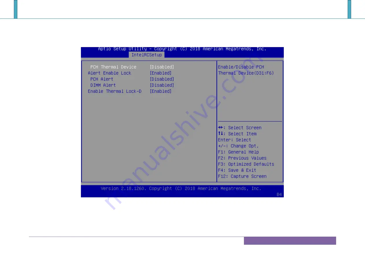
Page 136: ...COM Express PORTWELL PCOM B700G User s Guide Copyright PORTWELL 2018 PCOM B700G User s Guide 136 Platform Thermal Configuration ...
Page 137: ...COM Express PORTWELL PCOM B700G User s Guide Copyright PORTWELL 2018 PCOM B700G User s Guide 137 Miscellaneous Configuration ...
Page 138: ...COM Express PORTWELL PCOM B700G User s Guide Copyright PORTWELL 2018 PCOM B700G User s Guide 138 Server ME Debug Configuration ...
Page 139: ...COM Express PORTWELL PCOM B700G User s Guide Copyright PORTWELL 2018 PCOM B700G User s Guide 139 Server ME General Configuration ...
Page 140: ...COM Express PORTWELL PCOM B700G User s Guide Copyright PORTWELL 2018 PCOM B700G User s Guide 140 Override ICC Clock Enables ...
Page 141: ...COM Express PORTWELL PCOM B700G User s Guide Copyright PORTWELL 2018 PCOM B700G User s Guide 141 NM Configuration ...
Page 142: ...COM Express PORTWELL PCOM B700G User s Guide Copyright PORTWELL 2018 PCOM B700G User s Guide 142 Server ME Configuration ...
Page 143: ...COM Express PORTWELL PCOM B700G User s Guide Copyright PORTWELL 2018 PCOM B700G User s Guide 143 Runtime Error Logging ...
Page 144: ...COM Express PORTWELL PCOM B700G User s Guide Copyright PORTWELL 2018 PCOM B700G User s Guide 144 Whea Settings ...
Page 145: ...COM Express PORTWELL PCOM B700G User s Guide Copyright PORTWELL 2018 PCOM B700G User s Guide 145 Memory Error Enabling ...
Page 146: ...COM Express PORTWELL PCOM B700G User s Guide Copyright PORTWELL 2018 PCOM B700G User s Guide 146 IIO Error Enable ...
Page 147: ...COM Express PORTWELL PCOM B700G User s Guide Copyright PORTWELL 2018 PCOM B700G User s Guide 147 IIO Coherency Interface Error Enable ...
Page 148: ...COM Express PORTWELL PCOM B700G User s Guide Copyright PORTWELL 2018 PCOM B700G User s Guide 148 PCI PCI Error Enabling ...
Page 149: ...COM Express PORTWELL PCOM B700G User s Guide Copyright PORTWELL 2018 PCOM B700G User s Guide 149 Reserve Memory ...
Page 150: ...COM Express PORTWELL PCOM B700G User s Guide Copyright PORTWELL 2018 PCOM B700G User s Guide 150 6 5 Security ...
Page 151: ...COM Express PORTWELL PCOM B700G User s Guide Copyright PORTWELL 2018 PCOM B700G User s Guide 151 6 6 Boot ...
Page 152: ...COM Express PORTWELL PCOM B700G User s Guide Copyright PORTWELL 2018 PCOM B700G User s Guide 152 UEFI USB key Drive BBS Priorities ...
Page 153: ...COM Express PORTWELL PCOM B700G User s Guide Copyright PORTWELL 2018 PCOM B700G User s Guide 153 6 7 Event Logs ...
Page 154: ...COM Express PORTWELL PCOM B700G User s Guide Copyright PORTWELL 2018 PCOM B700G User s Guide 154 Change Smbios Event Log Settings ...
Page 155: ...COM Express PORTWELL PCOM B700G User s Guide Copyright PORTWELL 2018 PCOM B700G User s Guide 155 View Smbios Event Log ...
Page 156: ...COM Express PORTWELL PCOM B700G User s Guide Copyright PORTWELL 2018 PCOM B700G User s Guide 156 6 8 Save Exit ...
Page 157: ...evice I O Address Note Embedded Controller ITE8528 0x6E 0x6F EC Address 0x62 0x66 EC ACPI CMD Port 0x200 0x201 EC BRAM Port for I2C function 0x1300 0x13FF EC LPC IO Space 0x3F8 0x3FF EC UART1 0x2F8 0x2FF EC UART2 Carrier SIO 0x2E 0x2F W83627UGH Address 0x3F0 0x3F8 SIO UART1 0x2F0 0x2F8 SIO UART3 Table 12 System Resources ...
Page 158: ... PCOM B700G User s Guide Copyright PORTWELL 2018 PCOM B700G User s Guide 158 8 BIOS Update BIOS EC DOS Update SOP process Step 1 Create a DOS USB DOK Must be FAT or FAT32 format Step 2 Unzip update file to the DOS USB DOK ...
Page 159: ...M B700G User s Guide Copyright PORTWELL 2018 PCOM B700G User s Guide 159 Step 3 Plug the DOS USB DOK into the target system and boot from the DOS USB DOK Step 4 Under the update file folder type command update and press enter ...
Page 160: ...0G User s Guide Copyright PORTWELL 2018 PCOM B700G User s Guide 160 Step 5 The update process will start and you can see the updating progress Once finished please power off and restart the system End of BIOS EC DOS update process ...
Page 161: ...s PORTWELL PCOM B700G User s Guide Copyright PORTWELL 2018 PCOM B700G User s Guide 161 BIOS EC UEFI Update SOP process Step 1 Prepare a USB DOK Must be FAT or FAT32 format Step 2 Unzip update file to the USB DOK ...
Page 162: ...COM Express PORTWELL PCOM B700G User s Guide Copyright PORTWELL 2018 PCOM B700G User s Guide 162 Step 3 Select UEFI boot mode in the BIOS boot menu and save then restart the system ...
Page 163: ...COM Express PORTWELL PCOM B700G User s Guide Copyright PORTWELL 2018 PCOM B700G User s Guide 163 Step 4 Plug the USB DOK into the target system and boot from UEFI Shell ...
Page 164: ...0G User s Guide Copyright PORTWELL 2018 PCOM B700G User s Guide 164 Step 5 Under the UEFI shell direct to your USB DOK below is an example uses fs0 Then direct to the folder with updated file and type command update and press enter ...
Page 165: ...G User s Guide Copyright PORTWELL 2018 PCOM B700G User s Guide 165 Step 6 The updating process will start and you can see the updating progress Once finished please power off and restart the system End of BIOS EC UEFI update process ...
Page 166: ...TWELL BIOS web Tool PBT is a brand new on line utility innovated by PORTWELL PBT now is available for PORTWELL s premiere customers who are able to add customized BIOS logo and change BIOS default settings on American Megatrends AMI BIOS Please contact PORTWELL for more information PORTWELL EC Auto Test Tool PECAT The PORTWELL EC Auto Test Tool PECAT is a brand new utility innovated by PORTWELL PE...
Page 167: ...face Specification Revision 1 0 LPC http www intel com design chipsets industry lpc htm Universal Serial Bus USB Specification Revision 2 0 http www usb org home PCI Specification Revision 2 3 https www pcisig com specifications Serial ATA Specification Revision 3 0 http www serialata org PICMG COM Express Module Base Specification http www picmg org PCI Express Base Specification Revision 2 0 htt...