background image

13- ENG

A08193

Drain Valve (I):

 The drain valve is 

located at the base of the air tank and is 

used to drain condensation at the end of 

each use.

Cooling System (not shown)

:  This 

compressor contains an advanced 

design cooling system. At the heart of 

this cooling system is an engineered fan. 

It is perfectly normal for this fan to blow 

air over the pump head, cylinder sleeve, and crankcase. You know the cooling 

system is working when air is being expelled.

Air Compressor Pump (not shown):

  Compresses air into the air tank.  

Working air is not available until the compressor has raised the air tank 

pressure above that required at the air outlet.

Dipstick (J)

: Indicates the amount of oil in the pump, the 

+ mark indicates full and the - mark indicates oil needs to 

be added. See Oil paragraphs in the Maintenance section 

for instructions.

Motor Thermal Overload Protector (not shown):

 The 

motor has an automatic reset thermal overload protector. 
If the motor overheats for any reason, the overload 
protector will shut off the motor.  The motor must be 
allowed to cool down before restarting.  The compressor 
will automatically restart after the motor cools.

Air Intake Filter (K):

 This filter is designed to clean air 

coming into the pump. This filter must always be clean 
and ventilation openings free from obstructions. See 
"Maintenance".

Check Valve (L):

  When the air compressor is 

operating, the check valve is "open", allowing 
compressed air to enter the air tank.  When the air 
compressor reaches "cut-out" pressure, the check 
valve "closes", allowing air pressure to remain inside 
the air tank.

Pressure Release Valve (M):

  The pressure release 

valve located on the side of the pressure switch, is 

designed to automatically release compressed air from 

the compressor head and the outlet tube when the air 

compressor reaches "cut-out" pressure or is shut off. 

The pressure release valve allows the motor to restart 

freely. When the motor stops running, air will be heard 

escaping from this valve for a few seconds.  No air 

should be heard leaking when the motor is running, or 

continuous leaking after unit reaches "cut-out"  pressure.

M

N:\Manual Art\Air Comp\Art\ACC000401-450\Acc000402.eps

J

L

K

I

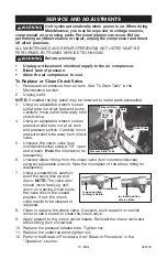
Summary of Contents for JOB BOSS C3550

Page 1: ...nstructions before starting operations Part No A08193 0410 0 ESPA OL P GINA 27 FRAN AIS PAGE 53 To learn more about Porter Cable visit our website at http www porter cable com Copyright 2004 Porter Ca...

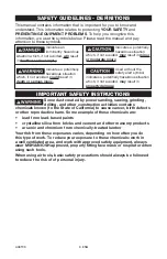
Page 2: ...the symbols below Please read the manual and pay attention to these symbols IMPORTANT SAFETY INSTRUCTIONS Some dust created by power sanding sawing grinding drilling and other construction activities...

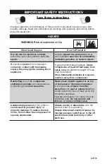
Page 3: ...roperty damage To reduce the risk of fire do not allow the compressor to operate unattended Always operate the compressor in a well ventilated area free of combustible materials gasoline or solvent va...

Page 4: ...ndensed water from tank causing rust and thinning of the steel tank Modifications or attempted repairs to the tank Unauthorized modifications to the unloader valve safety valve or any other components...

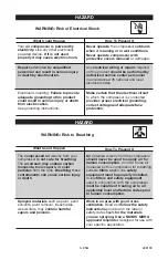
Page 5: ...ect voltage and adequate fuse protection The compressed air directly from your compressor is not safe for breathing The air stream may contain carbon monoxide toxic vapors or solid particles from the...

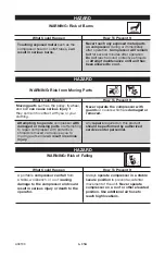
Page 6: ...thing WARNING Risk of Falling A portable compressor can fall from a table workbench or roof causing damage to the compressor and could result in serious injury or death to the operator Always operate...

Page 7: ...parts WARNING Risk of Unsafe Operation Unsafe operation of your air compressor could lead to serious injury or death to you or others HAZARD WARNING Risk of Serious Injury or Property Damage When Tran...

Page 8: ...ds to a certain high pressure before the motor automatically shuts off protecting your air tank from pressure higher than its capacity The high pressure at which the motor shuts off is called cut out...

Page 9: ...pressor life Use air compressor oil only NOTE Use an oil specifically formulated for use in an air compressor such as Porter Cable PAS1 air compressor oil Oil may be found at the store where the air c...

Page 10: ...not use if there are signs of damage 4 If these grounding instructions are not completely understood or if in doubt as to whether the compressor is properly grounded have the installation checked by...

Page 11: ...and minimum branch circuit requirements Certain air compressors can be operated on a 15 amp circuit if the following conditions are met 1 Voltage supply through branch circuit is 15 amps 2 Circuit is...

Page 12: ...ightly higher than the pressure switch cut out setting Outlet Pressure Gauge D The outlet pressure gauge indicates the air pressure available at the outlet side of the regulator This pressure is contr...

Page 13: ...d protector will shut off the motor The motor must be allowed to cool down before restarting The compressor will automatically restart after the motor cools Air Intake Filter K This filter is designed...

Page 14: ...he On Auto Off lever to ON AUTO position The compressor will start 6 Run the compressor for 20 minutes Make sure the drain valve is open and there is minimal air pressure build up in tank 7 After 20 m...

Page 15: ...te air regulation and control closer to the work area Reduce air pressure in tank to 60 psi maximum before removing or connecting portable control panel and when connecting hose to tank quick connect...

Page 16: ...efore performing any maintenance or repair disconnect power source from the compressor and bleed off all air pressure To Check Safety Valve If the safety valve does not work properly over pressurizati...

Page 17: ...visual signs of contaminants water dirt etc Make sure air vent C in dipstick is free from debris If air vent is blocked pressure can build in crankcase causing damage to air compressor and possible pe...

Page 18: ...in plug B 5 Slowly fill crankcase with oil Crankcase capacity is 6 fluid ounces 177 4 ml Oil level should be at the full mark on the dipstick Overfilling with oil will cause premature compressor failu...

Page 19: ...ir tank and pressure switch Carefully move pressure relief tube away from check valve 5 Unscrew the check valve turn counterclockwise using a 7 8 open end wrench Note the orientation for reassembly 6...

Page 20: ...ressure is approximately 20 psi Release safety valve ring 6 Drain water from air tank by opening drain valve on bottom of tank Water will condense in the air tank If not drained water will corrode and...

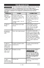
Page 21: ...gs where air can be heard escaping Check fittings with soapy water solution DO NOT OVERTIGHTEN Air leaks at fittings Air leaks at pressure switch release valve if equipped Defective pressure switch re...

Page 22: ...tenance section Pressure reading on the regulated pressure gauge if equipped drops when an accessory is used It is normal for some pressure drop to occur If there is an excessive amount of pressure dr...

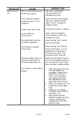
Page 23: ...load switch will automatically reset Tank pressure exceeds pressure switch cut in pressure Motor will start automatically when tank pressure drops below cut in pressure of pressure switch Loose electr...

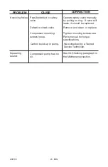
Page 24: ...ll leaks it should be replaced Compressor mounting screws loose Tighten mounting screws see Parts manual for torque specifications Carbon build up in pump Have checked by a Trained Service Technician...

Page 25: ...25 ENG A08193 NOTES...
Page 26: ...purchaser Air compressors with 60 and 80 gallon tanks will be inspected at the site of installation Contact the nearest Porter Cable Authorized Warranty Service Center that provides on site service c...

Reviews: