13
DGX-620/YPG-625
15.
Disassembling the Keyboard Assembly
15-1
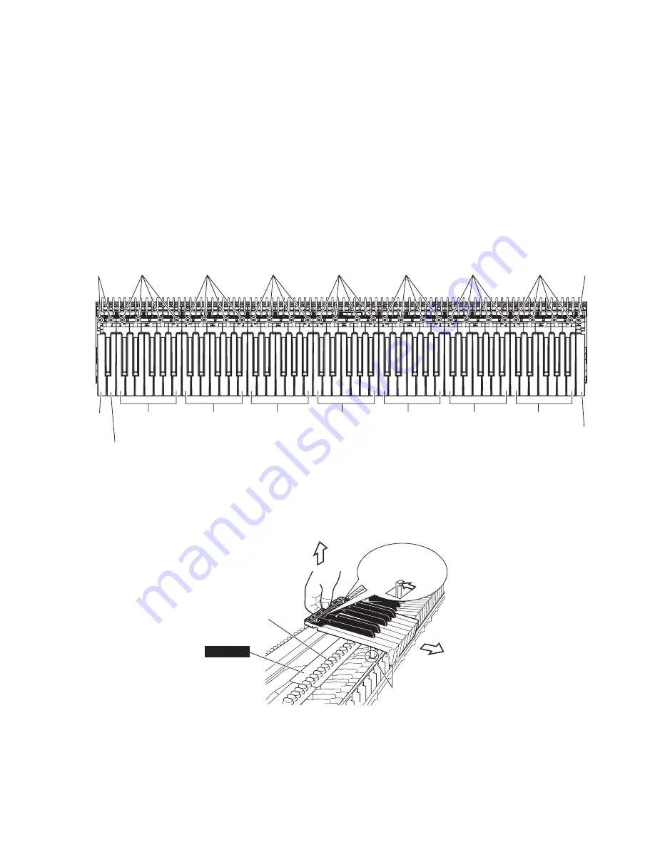
White key assembly and black key assembly
Remove the four (4) screws marked [270A] fixing the
black and white key assembly for one octave (C-B).
To remove the back of the black and white key assembly
of each octave, while pushing the end lug of white keys
rearward and lifting the back of keys, slide the black and
white key assembly towards you. (Fig.10, Fig.11)
Grease
Rubber contact
GHL88M
End lug of white key
[270B]
A-1 Key
B-1 Key
One octave
(C0-B0)
[270A]
[270A]
[270A]
[270A]
[270A]
[270A]
[270A]
[270C]
C7 Key
One octave
(C1-B1)
One octave
(C2-B2)
One octave
(C3-B3)
One octave
(C4-B4)
One octave
(C5-B5)
One octave
(C6-B6)
<Top view>
(Fig.11)
15-2
When removing white keys numbered as A-1 and B-1
key and black key, remove two (2) screws marked
[270B] and then lift the back of the keys and slide the
black and white keys towards you. (Fig.10)
15-3
When removing the C7 key, remove a screw marked
[270C] and then lift the back of C7 key and slide it
towards you. (Fig.10)
Note: When removing white key assembly and black key
assembly, be careful not to allow grease to attach to the
circuit board and rubber contacts, etc. (Fig.11)
(Fig.10)
[270]: Bind Head Tapping Screw-P 3.0X16 MFZN2W3 (WE973000)


