13
22
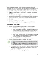
Click
Next
.
The
Phones
dialog box opens.
23
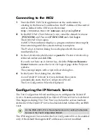
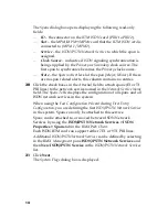
To define dial-in number ranges click the
Add
button.
24
In the
Add Phone Number
dialog box, define the first and the last
numbers in the phone number range.
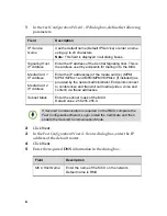
25
Click
OK
.
The new range is added to the
Dial-in Phone Numbers
table.
26
Optional
. Repeat steps
23
to
25
to define additional dial-in ranges.
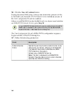
27
Enter the
MCU CLI
(Calling Line Identification).
With dial-in connections, the
MCU CLI
indicates the MCU’s
number dialed by the participant. In a dial-out connection,
indicates the MCU (CLI) number as seen by the participant.
28
Click
Save & Continue
.
After clicking
Save & Continue
, you cannot use the
Back
button to
return to previous configuration dialog boxes.
The ISDN/PSTN Network Service is created and confirmed.
29
Click
OK
to continue the configuration.
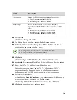
Line Coding
Select the PRI line coding method from the list.
•
For T1 spans, default is
B8ZS.
•
For E1 spans, default is HDB3.
Switch Type
Select the brand and revision level of switch
equipment installed in the service provider’s central
office.
•
For T1 spans, default is
AT&T 4ESS.
•
For E1 spans, default is
EURO ISDN.
•
A range must include at least two dial-in numbers.
•
A range cannot exceed 1000 numbers.
Field
Description


