background image

www.polkaudio.com

7

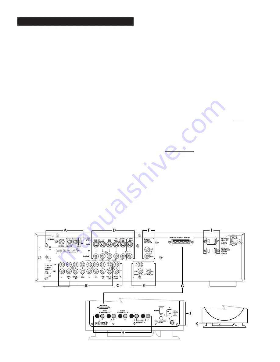
Area A—Antenna Connections

This is where you hook up indoor or outdoor antennas for AM and FM
radio reception.

Area B—Audio Analog Inputs/Outputs

This is where connections are made for the analog audio outputs of
sources such as CD player, DVD player, tape deck, etc. It is a good idea
to connect the analog outputs of all sources, even sources such as DVD
and Laserdisc players that have digital audio connections. Doing so
allows the use of digital sources for multi-room sound.

Area C—Multi-Room Outputs

These jacks allow you to use the sources (CD player, tape deck, etc.)
connected to the preamp/processor as sources of sound in another
room. See the section on “Using Multi Room” on page 25 of this manual. 

Area D—Video Inputs/Outputs

These jacks are used to feed the video signals of video players such as
VCR and DVD into the preamp/processor and then out to your TV. This
allows you to switch audio and video at the same time. For example,
when you want to switch from watching the VCR to watching the DVD,
you only have to push one button on the DS-2 remote instead of two
(one to switch audio on the DS-2 remote and one to switch video on the
TV remote).

There are two kinds of video jacks on the preamp/processor: standard
“composite,” and S-VHS (or S-video). If a video source and your TV have
S-video connectors, use them; you will get a picture with more detail.

IMPORTANT NOTE: If you connect a video source to the preamp/
processor with an S-video cable, you must connect the TV to the
preamp/processor with an S-video cable, or you will not see the 
picture on your TV.

See “Connection Precautions” on page 10.

Area E—Digital Inputs

This is where you connect sources with digital audio outputs, such as
DVD, 12" Laserdisc, and digital DSS receivers. 

IMPORTANT NOTE: The input jack labeled “LD RF” is for a Dolby
Digital RF signal from a 12" Laserdisc player only. Do not connect
a normal audio output terminal or the digital coaxial output of a
DVD player or any other source to the “LD RF” jack. You will 
damage the DS-2 if you do. 

Area F—Remote Control Extension Jacks

These jacks are for potential future Polk Audio products. When we bring
out other electronic products, these jacks will help you unify the remote
control functions of the DS-2 and the new device.

Area G—Multi-pin Connectors 

(on Preamp/Processor and Subwoofer)

These may look like connectors for computer printers, but they are not.
This is the way the 6 channels of sound get from the preamp/processor
to the 6 amplifiers that are built in to the subwoofer enclosure. We even
supply the cable. 

Area H—Speaker Connections 

(on Subwoofer)

This is where you hook up the speakers to the built-in amplifiers.  

Area I—AC Outlets

Connect the power cables of components such as a cassette deck and
CD player to these outlets. The one marked UNSWITCHED is always
live as long as the DS-2 is plugged into a live outlet. A component
connected here may be left on permanently, or may be switched off 
with its own power switch. Caution: In order to avoid potential turn-off
thumps, anything plugged in here should be turned on before the DS-2
is turned on. 

The outlet marked SWITCHED only delivers power if the DS-2 is on.
This is a good place to plug in any component that you want to turn on
and off along with the DS-2 system. Check the AC power rating of the
components you want to plug into these outlets. If either component
draws more than 0.8 Amperes of current, do not use these outlets.
Plug the component directly into a wall socket or power strip.  

Area J—Subwoofer AC Functions 

(on Subwoofer)

Once everything else is hooked up, set the switch to the “Standby” 
position. If the system fails to function, disconnect the subwoofer’s
power cord from the AC outlet, remove and inspect the fuse. Replace
with 7.5A Slow Blow 250V fuse only.

Area K—Pilot Light 

(on Subwoofer)

When the subwoofer is plugged in to a live AC outlet and the 
power switch (J) is set to “Standby” this light will glow red while
the preamp/processor is “off,” and green when the preamp
processor is “on.” 

REAR PANEL GUIDED TOUR

Summary of Contents for Digital Solution 2

Page 1: ...INSTRUCTION MANUAL DIGITAL SOLUTION 2 HOME THEATER SYSTEM DS 2 ...

Page 2: ...please read this manual thoroughly for information on getting the greatest enjoyment from your new system Designing high quality audio products is more than just a busi ness for the people of Polk Audio it is our passion We are all dedicated to your complete satisfaction and delight Should you have any problem or question regarding this or any Polk Audio product consult your Polk Audio dealer or c...

Page 3: ...on 2 was born This Digital Solution System is the ultimate all in one Home Theater System It s simply the best With the DS 2 you have everything you need except sources There s no need to choose a receiver or separate surround processor or multi channel power amplifier With the DS 2 you already have them They re built in And most importantly you know that they were designed specifically for each o...

Page 4: ...er This plug will fit into the power outlet only one way This is a safety feature If you are unable to insert the plug fully into the outlet try reversing the plug If the plug should still fail to fit contact your electrician to replace your obsolete outlet Do not defeat the safety purpose of the polarized plug 12 Power Cord Protection Power supply cords should be routed so that they are not likel...

Page 5: ...ng for the meaning of life The other half is looking for better bass This is as good as humor gets in the audio business If you are part of the latter group we ve got the subwoofer for you The DS 2 subwoofer uses our patented Power Port bass venting system to deliver deep powerful bass with low distortion Your friends will be green with envy Most folks like more bass on movies than music With the ...

Page 6: ...9 1 Remove all of the components and accessories from the shipping cartons 2 Connect sources such as DVD player VCR etc to the preamp processor audio and video inputs using coaxial RCA type cables 3 Connect the video output of the DS 2 preamp processor to a video input on your TV 4 Connect the preamp processor to the subwoofer with the supplied 4 meter DB 25 cable 5 Using the supplied speaker wire...

Page 7: ...the digital coaxial output of a DVD player or any other source to the LD RF jack You will damage the DS 2 if you do Area F Remote Control Extension Jacks These jacks are for potential future Polk Audio products When we bring out other electronic products these jacks will help you unify the remote control functions of the DS 2 and the new device Area G Multi pin Connectors on Preamp Processor and S...

Page 8: ...Polk Customer Service 800 377 7655 8 BASIC SYSTEM HOOK UP ...

Page 9: ...www polkaudio com 9 SPEAKER HOOK UP ...

Page 10: ...eamp processor We recommend that you also connect the Left and Right analog outputs of the DVD player to the analog audio DVD inputs of the preamp processor using RCA connectors This will allow you to tape record the audio output of the DVD player and use the DVD player as an audio source for a remote room Connect either the composite video or the S video output of the DVD player to the correspond...

Page 11: ...ght DSS inputs on the preamp processor This will allow you to record the audio output of the DSS on to a VCR If your DSS receiver does not have an optical digital output jack connect your DSS receiver to the DVD inputs as described in Connecting a DVD Player You will then connect your DVD player to the DSS inputs almost all DVD players have an optical output Connect either the composite video or t...

Page 12: ...er to get a picture with this input Connecting Your TV to the Preamp Processor If you are using only standard composite RCA video inputs for your video sources and no S video sources just connect the VIDEO TV out to any free composite video input of your TV If you are using only S VHS S video video inputs for your video sources and no standard composite sources just connect the VIDEO TV out to any...

Page 13: ...scribed above to connect the rear surround speakers to the Left Surround and Right Surround speaker outputs on the subwoofer amplifier Use the 40 12M wires IMPORTANT NOTE Be careful to maintain correct polarity on all the speakers by always using the speaker wire with the color insulator for the red terminals and the black marked wire for the black terminals ON THE AMPLIFIER AND ALL THE SPEAKERS F...

Page 14: ...side or slightly behind listener on wall Behind and to the sides of the listener on wall As above but placed on a stand or cabinet 3 ft or more in height As above but on a bookshelf with at least 8 clearance front and back Sound diffuse rear soundfield lean timbral balance convincing front to rear image flow slightly leaner balance richer midrange bal ance with some addi tional sonic coloration de...

Page 15: ...next page for an explanation of all those little teeny lights Volume Control Adjusts the overall sound level Turning the control clockwise increases the sound level turning it counter clockwise decreases the volume level Remote Sensor Window This window receives infrared signals from the remote control unit Aim the remote control unit to this sensor window Do not allow any solid object to block th...

Page 16: ...r Button When you want to clear a radio station from the list of presets select that preset station then press and hold the Clear button until CLEAR appears on the display See page 22 for more information on using this feature Presets Buttons These buttons select from the list of preset radio stations Pushing the button moves from lower preset numbers to the higher preset numbers Pushing the butto...

Page 17: ...h normal use Change the batteries as soon as you notice that the range of the remote control is decreasing REMOTE CONTROL OPERATION Remote Control Range The distance between the remote control transmitter and the preamp processor should be 15 feet 5 meters or less If the transmitter is pointed to a direction other than the IR SENSOR or if there is an obstacle between them the remote control may no...

Page 18: ...dio stations Pushing the right side of the rocker button moves from lower preset numbers to the higher preset numbers Pushing the left side of the rocker button moves down through the list of preset stations See page 22 for more information on using this feature H Late Night Button This button toggles between Late Night and Normal modes In the Late Night mode the dynamic range of the signal is red...

Page 19: ...ncel this procedure Re read the Subwoofer and Speaker Connections section of this manual and correct the wiring error before returning to this procedure 10 You will see a small square indicator cursor next to the current speaker Use the directional buttons on the remote to pick up the indicator and move it to the next speaker in the array Center 11 The test tone should now come from the center spe...

Page 20: ... defaults return to this on screen menu select DEFAULTS ON save and exit The factory settings will be restored Front Minus Surround Dolby Digital Pro Logic Distance feet Surround Delay Setting Surround Delay Setting 1 3 feet 5ms 15mS 4 6 feet 5ms 20mS 7 11 feet 10ms 25Ms 12 feet or more 15ms 30mS Setting Dolby Pro Logic Delay The channel delay function for Dolby Pro Logic exists for a somewhat dif...

Page 21: ...eception of distant FM stations you will need a better FM antenna Your Polk Audio dealer can recommend a high quality indoor or outdoor FM antenna Be sure to get one with a 75 Ohm coaxial output If you already have a TV roof antenna you can use it for the FM tuner Get a signal splitter from a radio TV dealer or Radio Shack store It will allow you to use the same antenna for TV and FM radio recepti...

Page 22: ...imultaneously for more than 3 seconds CAUTION The all memory clear operation clears all memory including the volume level and surround mode memory and turns the power OFF Playing a DVD or other audio video source 1 Turn unit on by pressing POWER button A 2 Push the DVD input button J on the remote or use the SOURCE buttons on the front panel B to toggle through the sources until the display reads ...

Page 23: ...r is no Dolby Digital is a digital audio compression system that provides very high fidelity sound quality in either 2 or 6 channels The six channels are Left and Right front Center Left and Right rear and a Low Frequency Effects channel or 5 1 The vast majority of Dolby Digital program materials are 5 1 multi channel recordings Most DVDs have both 2 channel and 5 1 channel Dolby Digital soundtrac...

Page 24: ...ove the cursor down to the EXIT line Press the Enter button on the remote control to save and exit this menu The preamp processor will now go back to normal operation USING MULTI ROOM FEATURE Operating from the Front Panel 1 Push the MULTI ROOM button on the front panel of the preamp processor 2 The red MULTI indicator will blink and the words SEL SOURCE will appear on the display 3 Push the eithe...

Page 25: ...is a 5 1 disc and it still isn t delivering 5 1 Still no 5 1 Call your Polk dealer or Polk Audio This will definitely fix the problem Try this Make sure the subwoofer is plugged in to a live AC outlet and that the power switch on the back of the sub is set to Standby Make sure the 4 meter cable that connects preamp processor and subwoofer is firmly inserted and screwed in Make sure the MUTE light ...

Page 26: ...riginal purchaser only that the Preamp Processor and Amplifier in this Polk Audio Loudspeaker Product the Product will be free from defects in material and workmanship for a period of three 3 years from the date of original retail purchase from a Polk Audio Authorized Dealer Polk Audio Inc further warrants to the original purchaser only that the Loudspeaker s in this Polk Audio Product the Product...

Page 27: ...ypropylene cone and butyl rubber surround Crossover design Fixed active 4th order 24dB octave low pass with amplitude shaping Cabinet Dimensions 183 4 H x 151 2 W x 191 2 D Six Channel Power Amplifier System Continuous Power Output Greater than 500 Watts into 4 Ohms all channels driven Dynamic Power Output 700 watts into 4 Ohms all channels driven Bandwidth 20Hz 22kHz Distortion 0 05 Power Require...

Page 28: ...28 OVERALL HOOK UP ...

Page 29: ...29 Polk Customer Service 800 377 7655 www polkaudio com ...

Page 30: ...www polkaudio com 30 ...

Page 31: ...Polk Customer Service 800 377 7655 31 ...

Page 32: ...5601 METRO DRIVE BALTIMORE MARYLAND 21215 USA 410 764 5275 FAX 410 764 5266 www polkaudio com RM6705 1 ...

Reviews: