16
When BDOI testing and calibration are finished, the BDOI LCD will indicate a connected
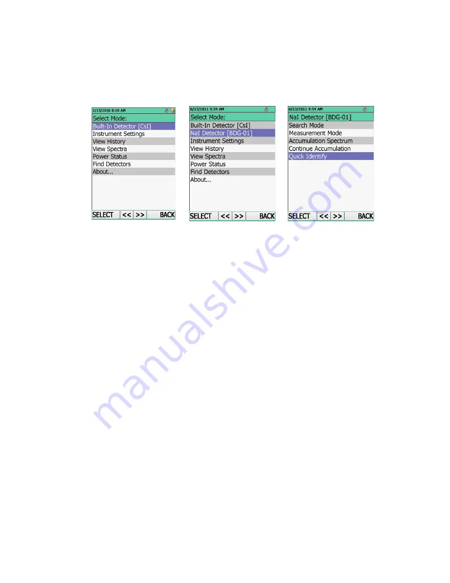
BDG1 external detector, in the line "Detector NaI [BDG1]", Figure 6.3 (2).
If BDG1 is connected to the switched on BDOI, then in the indication mode of the BDOI
operation modes select the "Find Detectors" line, Figure 6.3 (1).
To enter the indication mode of the BDG1operation modes: select the "Detector NaI [BDG1]"
line. A window displaying the operation modes of BDG1will be opened, Figure 6.3 (3).
1)
2)
3)
Figure 6.3
Use keypad to control BDOI (Figure 6.2).
BDG1 is switched on and ready for operation.
BDG1 switches off when the cable is disconnected from it, or after BDOI is switched off.
To switch BDOI off: press key ON/OFF and wait till the BDOI switches off.
6.2
Operability control BDG1
Switch on BDG1 as stated in 6.1. Green LED must light on the BDG1 front panel.
Check every BDG1 operation mode operability:
LED lights green – indicates that the BDG1 test mode is activated (Figure 4.1, position 1);
LED lights yellow – indicates that the BDG1 calibration mode is activated (Figure 4.1,
position 1);
Switch off BDG1 as stated in 6.1.
6.3
Connect BDG1 to PC
Connect BDG1 to the USB port of the working PC using the cable # 3.
BDG1-PC operation procedure is described in the user program supplied on the CD.
Start user program. Switch BDG1 into the measurement mode of photon radiation DER.


