background image

Stand and Control Box Removal 

Lay TV flat on workbench. Be careful to protect the front bezel and LCD screen from being scratched. Use 
protective cloth between work bench and TV front. 
 

Note:  Before disassembly of any part the TV, make sure the power is OFF, and the 
power cord is removed from the wall outlet. Allow time for power within all system 
boards to discharge before you begin disassembly. Never insert any objects into the 
vent holes in the TV case. 


(1)


Remove 4 screws (A) from the TV Stand. 


(2)


Remove 3 screws (A) from the Control Box Cover, and remove the Cover from the TV. 


www.polaroid.com 

23

A

A

Summary of Contents for 4011-TLXB - 40" LCD TV

Page 1: ...2007 LCD Models North America TLA 04011C TLXB 4011 TLXB 4241 SERVICE MANUAL Bezel covers vary by model 20070613 ...

Page 2: ...t the plug into the outlet contact your electrician to replace your obsolete outlet Do not ignore the purpose of the grounding type plug 10 Do not allow anything to rest on the power cord Do not locate this product where people will walk on the cord 11 If an extension cord is used with this product make sure that the total of the ampere ratings on the product plugged into the extension cord does n...

Page 3: ...gs because only the inside of the bags provide electrostatic protection Always hold components by their edges Avoid touching the edge connectors Never slide components over any surface Wear a grounding wrist strap available at most electronics stores and attach it to a bare metal part of your workbench or other grounded connection Touch a bare metal surface on your workbench or other grounded obje...

Page 4: ... ONLY use lead free solder that matches the symbol on the component Using conventional lead solder may lead to damage or a short which could result in fire electric shock or other hazards Because the melting point of lead free solder is higher than conventional lead solder observe the following guidelines when soldering with lead free solder 1 Always use a dedicated soldering bit for different typ...

Page 5: ...o the User 21 6 Disassembly Procedure 22 Stand and Control Box Removal 23 Rear Cabinet Cover LCD Panel and Front Bezel 25 IR Board Removal and Replacement 32 Front Side Control Buttons Removal and Replacement 33 7 Spare Parts Lists 34 8 Exploded View Diagram 36 9 Block Diagram 37 10 Schematics 38 11 PCB Layout Diagrams 47 Model Specifications are located in User Manual Go to polaroid com to obtain...

Page 6: ...ite x 0 280 y 0 290 Response Time 8ms Gray to Gray Surface Treatment Haze 40 Hard Coating 3H TLXB 4241 Item Specifications Panel Model No V420H1 L05 Display pixels 1920 H x 1080 V pixels 1 pixel 1 RGB cell Display Area 36 6 in H x 20 6 in V 930 24mm H x 523 26mm V Pixel Pitch 0 1615 H x 0 4845 V Display Colors 16 7M Pixel Arrangement R G B vertical stripe Brightness 500cd m2 typical Contrast Ratio...

Page 7: ...r1 Component Y Pb Cb Pr Cr L RAudio 480i 480p 720p 1080i RCA VIDEO4 YPbPr1 YPbPr2 Component Y Pb Cb Pr Cr L RAudio 480i 480p 720p 1080i HDMI1 HDMI Digital RGB Digital Audio HDMI 19 Pin VIDEO6 HDMI1 HDMI2 HDMI Digital RGB Digital Audio HDMI 19 Pin VIDEO7 HDMI2 VGA VGA L REarphone L R Audio RCA STEREO AUDIO OUT A C R K N I L S O T L A I X A O C l a c i t p O l a t i g i D DIGITAL ACIN ACPower IN AC1...

Page 8: ... 75 DDC1 2B Compliant with Revision 1 0 e t a r a p e s V H c n y S 3VTTLlevel 1k Fv 56 76Hz Maximum Pixel Clock 135Mhz Connector Mini D Sub 15 pin female x 1 Video Composite CVBS Signal Format NTSC 4 43NTSC PAL_M PAL B G H D N SECAM Level Impedance 1 0Vp p 75 S Video Y C Signal Format Y C C 286mV 75 Analog HD15 Video Signal YPbPr YCbCr Format Y Pb Pr or Y Cb Cr Pb Cb Pr Cr 0 7 0 035Vp p 75 HDMI T...

Page 9: ... 0 6 4 2 0 1 x 0 8 2 1 A G X S 5 3 1 0 8 5 7 4 2 0 1 x 0 8 2 1 A G X S 4 2 0 3 5 3 7 6 0 8 4 x 0 4 6 C A M Video S Video AV Timing STANDARD RESOLUTION V FREQ Hz H FREQ kHz CLK MHz 5 6 2 1 4 3 7 5 1 0 6 5 2 5 C S T N 0 5 4 1 5 2 6 5 1 0 5 5 2 6 M A C E S 5 6 2 1 4 3 7 5 1 0 6 5 2 5 M L A P 0 5 4 1 5 2 6 5 1 0 5 5 2 6 N L A P HDTV Component AV Timing 7 2 5 1 3 0 6 0 8 4 x 0 2 7 p 0 8 4 V T D S 2 4 7...

Page 10: ...www polaroid com 10 2 Operation ...

Page 11: ...www polaroid com 11 ...

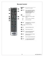
Page 12: ...Remote Control www polaroid com 12 ...

Page 13: ...www polaroid com 13 ...

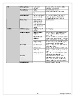
Page 14: ...GA mode H Position Adjusts the position of the picture left and right in the window V Position Adjusts the position of the picture up and down in the window CLOCK Controls the width of the picture based on the VGA mode VIDEO VGA Phase Controls the signal phase It can improve the focus clarity and image stability based on the VGA mode Bass 0 100 50 Fine tune the bass value Treble 0 100 50 Fine tune...

Page 15: ...basic analog closed caption options OFF CC1 CC2 CC3 CC4 Digital Closed Caption Select one of the digital closed caption options Service1 Service2 Service 3 Service4 Service5 Service6 OFF Closed Caption Caption Style Customize the settings for the digital closed caption option selected Input Password Enter a 4 digit pin code The default pin code is 0000 Channel Lock Set the channel that you want to...

Page 16: ...ental Controls V Chip The factory preset password is 0000 This password must be used first before setting your own personal password It is recommended that you keep your personal password in a safe place and away from children In the event you loose your personal password the master password is 8202 The master password overrides all passwords The master password can t be changed and should be kept...

Page 17: ...www polaroid com 17 ...

Page 18: ...www polaroid com 18 ...

Page 19: ...www polaroid com 19 ...

Page 20: ...l defect defect in which the cell is always off 2 Non extinguishing or bright cell defect defect in which the cell is always on The Polaroid Display Cell Defect Specifications below define the allowed limits for display cell defects and are used as the criteria in determining whether an LCD panel is replaced 7 or more defective pixels across the entire LCD screen Polaroid will repair replace LCD p...

Page 21: ...k ohm 10 watt resistor paralleled by a 0 15 µF capacitor c Using an AC voltmeter sensitivity of 5000 ohm per volt or higher measure the voltage drop across the test circuit between all exposed metallic parts and a known earth ground Measurement points include antenna metal cabinet parts screw heads and metal knobs or controls Measurement points can vary slightly even between revisions of the same ...

Page 22: ...a cable unplug the cable before removing the screws to avoid damaging the cable Use a magnetized screwdriver for removing screws To help keep track of screws place each component s screws next to the component on your work surface ELECTROSTATIC DISCHARGE ESD Components inside an LCD or plasma TV are sensitive to static electricity Before servicing the TV follow these guidelines Avoid static causin...

Page 23: ...isassembly of any part the TV make sure the power is OFF and the power cord is removed from the wall outlet Allow time for power within all system boards to discharge before you begin disassembly Never insert any objects into the vent holes in the TV case 1 Remove 4 screws A from the TV Stand 2 Remove 3 screws A from the Control Box Cover and remove the Cover from the TV www polaroid com 23 A A ...

Page 24: ...l Box Unplug the 2 cables A from the Control Box and remove the Box from the TV Remove all remaining foam and aluminum foil and save for re use Note Before returning this product to the end user you must follow the steps outlined in the section Before Returning This Product to the User on page 21 This procedure ensures that the chassis will not cause electric shock www polaroid com 24 A A ...

Page 25: ...boards to discharge before you begin disassembly Never insert any objects into the vent holes in the TV case Note OEM LCD panels were used in production The following LCD panel disassembly removal instructions may not apply to all models Ensure LCD panel is completely detached from the bezel before removing so the bezel is not damaged 1 Remove 6 screws A from the rear cabinet cover www polaroid co...

Page 26: ... 2 Remove 5 screws A from between the bezel and rear cabinet cover and remove the rear cabinet cover from the TV 3 Remove 4 screws A from the bottom of the cabinet www polaroid com 26 A A ...

Page 27: ... 4 Remove the foam and aluminum foil A and SAVE for reassembly 5 Remove 2 screws A from the D sub plate and unplug cable www polaroid com 27 A A ...

Page 28: ...d remove AV assembly B A B 7 Remove 8 screws A from right bracket then do the same for the left and remove brackets A 8 Remove 4 screws A from right side panel and then do the same on the left panel and remove panel from bezel www polaroid com 28 A A ...

Page 29: ...aluminum A saving it for reassembly from both side supports 10 On the left support bracket remove 2 screws A from each end of the bracket and 2 screws B from the center Remove bracket Repeat procedure on the right bracket 9 A B A ...

Page 30: ...oid com 30 12 Unplug the in 13 Remove the 11 On left end remove 6 screws A Repeat procedure on right side verter cable A and remove it 4 screws 4 on the right speaker Repeat procedure for the left speaker A A A ...

Page 31: ... avoid damage TWO PEOPLE ARE REQUIRED to lift the LCD Panel from the TV oduct to the end user you must follow the steps outlined in the section Before Returning This Product to the User on page 21 This procedure ensures that the chassis will not cause electric shock Note Before returning this pr A ...

Page 32: ...es in the TV case 1 Disassemble control box cover and rear cabinet cover 2 Remove 8 screws A from front bezel and net cover 2 screws A from the IR Board and remove the board from the TV Note Before returning this product to the end user you must follow the steps outlined in the section Before Returning This Product to the User on page 21 This procedure ensures that the chassis will not cause elect...

Page 33: ...pla Note Before disassembly of any part the TV make sure the power is OFF and the power cord is removed from the wall outlet Allow time for power within all system boards to discharge before 1 Disassemble control box cover and rear cabinet cover Note Before returning this product to the end user you must follow the steps outlined in the section Before Returning This Product to the User on page 21 ...

Page 34: ... R 845 C45 GF1XA PEH 26 46 UNIVERSAL REMOTE SILV BLK 899 A00 GF271XAH 26 46 FRONT SIDE AV INPUT BD 899 E00 GF271XAH 26 46 IR BOARD ASSY 899 K00 GF271XAH 26 46 FRNT SIDE CONTROL BTN BD 909 KS2 GF4012XAPH 40 CNTRL BX SAMSUNG Polaroid Model 4011 TLXB Part Number Description 125 000 375POLAH POLAROID LOGO 151 001 FU67G AH REAR CABINET 151 700 GF421UABH 40 STAND ASSY BLK SILV 151 A00 FU68B7WH FRNT BZL ...

Page 35: ...5 26 46 FRNT SIDE C R BLK 00 GF370H NTRL BTN CV 600 AC 181 3200 LIH POWER CORD 621 CO CBL 181 2000H MPOSITE VIDEO 631 LV 030 GF421XA CH DS CABLE 70 42 5 5 542 001CH LCD PANEL CMO L0 824 SP 020 A002H EAKER L R 845 26 BLK C45 GF1XA PEH 46 UNIVERSAL REMOTE SILV 899 26 D A00 GF271XAH 46 FRONT SIDE AV INPUT B 899 E IR 00 EF321XPH BOARD ASSY 899 CN RT K00 GF271XAH TRL BUTTON BD F 909 42 CNTRL BX CMO L05...

Page 36: ...8 Exploded View Diagram www polaroid com 36 ...

Page 37: ...www polaroid com 37 9 Block Diagram ...

Page 38: ...www polaroid com 38 10 Schematics Power ...

Page 39: ...www polaroid com 39 VGA Input ...

Page 40: ...www polaroid com 40 YPBR Input ...

Page 41: ...www polaroid com 41 HDMI Input ...

Page 42: ...AV SV Inpu www polaroid com 42 www polaroid com 42 t ...

Page 43: ...Tuner Input www polaroid com 43 ...

Page 44: ...www polaroid com 44 www polaroid com 44 D Board IR Sensor LE ...

Page 45: ...Data 0 15 DDC CLK 8 TMDS Data 0 shield 16 DDC DATA D Sub Connector IN This function also can provides to HDTV D Sub type Connector pin assignment 1 Red Video 6 Red Ground 11 GND 2 Green Video 7 Green Ground 12 SDA For DDC1 2B 3 Blue Video 8 Blue Ground 13 H sync 4 GND 9 5V from PC 14 V sync 5 Vdd from PC for DDC 10 Sync GND 15 SCL For DDC1 2B RCA jacks are all female type Mini DIN CNC 4 Pins SCN57...

Page 46: ...polaroid com 46 Pin Pin Pin Assignment Assignment Assignment 1 6 Red Ground 11 Ground Red 2 Green 7 Green Ground 12 SDA 3 Blue 8 Blue Ground 13 Horizontal Sync 4 Ground cted 14 Vertical Sync 9 Not Conne 5 0 15 SCL Self Test 1 Sync Ground ...

Page 47: ...www polaroid com 47 11 PCB Layout Diagrams Keypad Board Component Side Top Bottom Keypad Board Component Side IR LED Board nent Side Top Compo Board Component Side Top AUX AV ...

Page 48: ...www polaroid com 48 D SUB 37 Pin Board Component Side Top ...

Reviews: