www.polaroid.com
21
5.
Before Returning This Product to the User
Before returning this product to the user, always perform the following safety checks:
(1)
Inspect all wiring to be sure no wires are pinched between the chassis or any metal parts.
(2)
Inspect all protective devices for proper installation, including non-metallic controls, insulation materials, cabinet
backs, compartment covers, and shields.
(3)
Verify that no shock hazard exists on any part of the chassis, especially any metal components including cable
connection points, chassis hardware, or antennas (if equipped). Use the following procedure:
a.
Plug the AC cord directly into a 120 V AC outlet.
b.
Create a test circuit consisting of a 1.5k ohm, 10
watt resistor paralleled by a 0.15 µF capacitor.
c.
Using an AC voltmeter (sensitivity of 5000 ohm per
volt or higher), measure the voltage drop across
the test circuit between all exposed metallic parts
and a known earth ground. Measurement points
include antenna, metal cabinet parts, screw heads,
and metal knobs or controls. Measurement points
can vary slightly even between revisions of the
same model, so always conduct a thorough review
of the chassis to locate metal points that a user
may touch.
d.
Any voltage reading of 0.375 Vrms AC (0.25
mArms) or higher indicates a potential shock
hazard.
THIS CONDITION MUST BE
CORRECTED BEFORE RETURNING THE
PRODUCT TO THE USER!
e.
Repeat the above checks with the AC polarity
reversed. A non-polarized adapter is required to
reverse the polarity; DO NOT LEAVE THIS
ADAPTER WITH THE USER! Under normal
operation the product must use the proper polarity.
Summary of Contents for 4011-TLXB - 40" LCD TV
Page 10: ...www polaroid com 10 2 Operation ...
Page 11: ...www polaroid com 11 ...
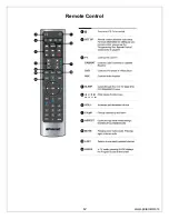
Page 12: ...Remote Control www polaroid com 12 ...
Page 13: ...www polaroid com 13 ...
Page 17: ...www polaroid com 17 ...
Page 18: ...www polaroid com 18 ...
Page 19: ...www polaroid com 19 ...
Page 36: ...8 Exploded View Diagram www polaroid com 36 ...
Page 37: ...www polaroid com 37 9 Block Diagram ...
Page 38: ...www polaroid com 38 10 Schematics Power ...
Page 39: ...www polaroid com 39 VGA Input ...
Page 40: ...www polaroid com 40 YPBR Input ...
Page 41: ...www polaroid com 41 HDMI Input ...
Page 42: ...AV SV Inpu www polaroid com 42 www polaroid com 42 t ...
Page 43: ...Tuner Input www polaroid com 43 ...
Page 44: ...www polaroid com 44 www polaroid com 44 D Board IR Sensor LE ...
Page 48: ...www polaroid com 48 D SUB 37 Pin Board Component Side Top ...


