Polaris UniversalLUXX Installation Manual Download Page 12

1300 555 514                                                                                                                                                                                                  12


Steering Wheel Controls 


Steering wheel controls should work for all non CAN bus vehicles provided that Key 1, Key 2 and steering 
wheel ground have been hardwired in properly according to your specific vehicle. 


Some CAN bus vehicles will work with a specific module, please call Polaris to see if we have a solution for 
your vehicle. 


Programming in your steering wheel controls 


Select Wheel Key study from the main menu 


Select and press one of your steering wheel controls. 


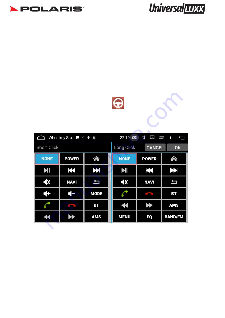
Once you have selected one of your steering wheel controls, the following screen will 
appear: 


You can select a different function for short click and long click. 


For example, if I have selected my mode button, I can select the mode function as my 
short click and then I can choose the 

ok google

’ 

function for my long click. When I hold 

down my mode button, 

ok google

’ 

will appear.


Once you have your desired settings, press ok in the top right hand corner. You will then 
be taken back to the SWC Home screen. Select the next steering wheel control that you 
wish to programme in and follow the same procedure. 


Keep repeating the same procedure to programme each individual SWC setting. 


Summary of Contents for UniversalLUXX

Page 1: ...1300 555 514 Installation Manual Please read this manual before installing this product ...

Page 2: ...damaged or tampered with in any way this includes installing foreign mapping or software onto the SD card The installation of 3rd party apps that may cause harm to the unit Warranty Terms The UniversalLUXX is covered 2 years and includes Defective Equipment Defective Cables Not Covered under warranty Abuse Improper installation Alteration to Cables includes cutting of any cables Accidents Water da...

Page 3: ...ing Diagrams 8 9 Additional camera wiring diagram 10 Mounting the head unit 11 Steering Wheel Controls 12 13 Dimensions 14 Returns Procedure 15 Please note once the unit is installed you can access your user manual on the head unit or you can download a copy from our website www polarisgps com au Also check out our youtube channel Polaris GPS for troubleshooting tutorials Record your serial number...

Page 4: ...e is disconnected before installation To avoid possibility of shorting out the electrical circuit in the unit never connect the battery wire directly to the vehicle battery Always secure all wirings with cable clamps or adhesive tape to prevent short circuit Please make sure all wiring connections and speaker wires are well insulated When pulling the dash apart please use quality trim tools to avo...

Page 5: ...Speaker right front 6 Grey with black stripe Speaker right front 7 Purple Speaker right rear 8 Purple with black stripe Speaker right rear 9 Red 12V to ignition ACC power On 10 Black Ground 11 Blue Auto Antenna Control 12 Orange Illumination Dimmer 13 Yellow 12V to battery The Universal Luxx comes with a universal ISO connector This means that you can purchase a secondary harness for certain model...

Page 6: ...1300 555 514 6 Wiring Diagram ...

Page 7: ... Toyota Vehicles Toyota Power Harness Optional Extra Special Vehicle Notes Radio Reception for Toyota vehicles with a standard radio connection For all Toyota vehicles that use the older style one pin Radio Antenna plug you will need to attach either the Antenna control wire or the Amp Control wire from the Toyota power loom to the Antenna Control wire on the Toyota OEM plug Attach the amp control...

Page 8: ...BRANDS AND MODELS Acc CUT AND TAPE OFF WIRES AS NOT NEEDED IN THIS SET UP AS NOT NEEDED IN THIS SETUP RCA PLUGS INTO CAMERA INPUT FOUND ON HEAD UNIT CONSTANT CAMERA AND TRIGGER DIAGRAM 1 Head REVERSE TRIGGER POWER FROM REVERSE LIGHTS RCA PLUGS INTO CAMERA INPUT FOUND ON HEAD UNIT RCA CAMERA WITH REVERSE TRIGGER ONLY DIAGRAM 2 ...

Page 9: ...S NOT NEEDED IN THIS SET UP RCA PLUGS INTO CAMERA INPUT FOUND IF NO REVERSE TRIGGER IS FOUND PLEASE FOLLOW THE SECOND DIAGRAM IF YOU WOULD LIKE A CONSTANT CAMERA AS WELL A TRIGGER MUST BE BROUGHT FROM REVERSE LIGHT POWER TO CAMERA DIAGRAM 3 Wiring Diagram Reverse Camera cont ...

Page 10: ...second camera you would normally select the return touch button however the universal luxx does not have a return button so you will need to program your home button as a return function as well To do this go into settings Car settings Factory settings type in 126 select KEY select Touch key study select clear then start the process of touching your eject touch button then select the eject symbol ...

Page 11: ...ach the screen and test all functions Some vehicles will require a fascia to fill the gap around the Universal double din chassis Do not forget to remove the transportation screws before installing Some OEM brackets may have to be modified in order to line the brackets up on the Universal Luxx Some fascias may also have to be modified for the Universal Luxx to fit neatly ...

Page 12: ...ontrols Once you have selected one of your steering wheel controls the following screen will appear You can select a different function for short click and long click For example if I have selected my mode button I can select the mode function as my short click and then I can choose the ok google function for my long click When I hold down my mode button ok google will appear Once you have your de...

Page 13: ...ume up Volume down Mode Radio Mute Bluetooth Answer Hang Up Brightness Ok Google Skip Back Skip Forward Rewind Fast Forward On off Sound Equalizer Settings Steering Wheel Control functions Power standby Answer call Settings Home main menu Hang up call AV in Return Brightness control Equaliser Widgets Ok Google Radio Scans through pre sets Volume Up Stop music movies files Radio Scans Volume Down S...

Page 14: ...1300 555 514 14 Dimensions 179mm 101mm 15cm 17 5cm 104mm Lip behind 182mm Lip behind ...

Page 15: ... settings or running a software update 2 If our technician has exhausted all options and determines that the unit needs to be sent back for assessment please visit www polarisgps com au warranty returns returns form Please print and fill out the return form and include a copy with the goods For a speedy return process please try and be as detailed as possible when describing the fault 3 Package th...

Reviews: