background image

161

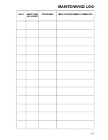
MAINTENANCE LOG

DATE

MILES (KM)

OR HOURS

TECHNICIAN

SERVICE PERFORMED / COMMENTS

Summary of Contents for Sportsman XP 1000

Page 1: ...an adult vehicle only Operation is prohibited for those under 16 years of age Owner s Manual for Maintenance and Safety 2017 Scrambler 1000 Scrambler XP 1000 Scrambler XP 1000 Zugmachine Sportsman 10...

Page 2: ...1 2017 Owner s Manual Scrambler 1000 Scrambler XP 1000 Sportsman 1000 Sportsman XP 1000 Sportsman XP 1000 Zugmachine Sportsman Touring XP 1000...

Page 3: ...nor discrepancies may result between the actual vehicle and the information presented in this publication Depictions and or procedures in this publication are intended for reference use only No liabil...

Page 4: ...ntroduction 4 Safety 8 Features and Controls 27 Operation 62 Winch Guide 83 Emission Control Systems 95 Maintenance 96 Troubleshooting 143 POLARIS Products 147 Specifications 148 Warranty 156 Maintena...

Page 5: ...s manual The manual contains instructions for minor maintenance but information about major repairs is outlined in the POLARIS Service Manual and should be performed only by a factory certified Master...

Page 6: ...tuation that if not avoided will result in death or serious injury WARNING A WARNING indicates a hazardous situation that if not avoided could result in death or serious injury CAUTION A CAUTION indic...

Page 7: ...ECTIVES TEST EVALUATION METHODS 2006 42 EC as amended Machinery Directive EN 15997 2004 108 EC as amended EMC Directive UNECE R10 97 24 EC Chapter 8 MODEL COMMERCIAL NAME SERIAL NUMBER A_ _SX _ 95_ _...

Page 8: ...using your key number and mating it with one of your existing keys The ignition switch must be replaced if all keys are lost Vehicle Model Number ___________________________________________________ Fr...

Page 9: ...death This POLARIS vehicle is not a toy and can be hazardous to operate A collision or rollover can occur quickly even during routine maneuvers if you fail to take proper precautions Read and understa...

Page 10: ...d Equipment Modifications The warranty on your POLARIS vehicle may be terminated if any equipment has been added or if any modifications have been made that increase speed or power The addition of cer...

Page 11: ...training from a certified instructor Never permit others to operate the vehicle unless they have read and understand this manual and all product labels and have completed a certified safety training c...

Page 12: ...d long pants Never consume alcohol or drugs before or while operating this vehicle Operating this ATV on public streets could result in a collision with another vehicle Never operate an off road vehic...

Page 13: ...met that fits properly Wear eye protection goggles or face shield gloves boots long sleeves and long pants Never operate at excessive speeds Travel and turn at speeds appropriate for the terrain visib...

Page 14: ...h hands on the passenger grab handles at all times The passenger should never hold on to the operator Always travel slowly when operating on unfamiliar terrain Use extra caution Always follow the proc...

Page 15: ...too steep for the ATV or for your abilities Never operate a 1 up ATV on hills steeper than 25 Never operate a 2 up ATV on hills steeper than 15 Always follow the procedures outlined in this manual for...

Page 16: ...for operating over obstacles See page 72 Always follow the procedures outlined in this manual for operating on slippery or loose surfaces Use extra caution Always avoid skidding or sliding See page 7...

Page 17: ...capacity for your vehicle Cargo must be properly distributed and securely attached Reduce speed and follow the instructions in this manual for carrying cargo or towing Allow a greater distance for br...

Page 18: ...bear a U S Department of Transportation DOT label Approved helmets in Europe Asia and Oceania bear the ECE 22 05 label The ECE mark consists of a circle surrounding the letter E followed by the distin...

Page 19: ...sonal Protective Equipment PPE bearing markings such as VESC 8 V 8 Z87 1 or CE Make sure protective eye wear is kept clean Gloves Off road style gloves with knuckle pads are the best for comfort and p...

Page 20: ...ears of age to operate this vehicle Wear approved helmet goggles and protective clothing Never use alcohol or drugs before or while operating NEVER carry a passenger This vehicle is approved for onroa...

Page 21: ...EAR 45 kPa 0 5 bar Clutch Cover Alert 7181427 Keep body parts away from belt Rack Alert 7181582 DO NOT TOW FROM RACK OR BUMPER Tow only from tow hooks or hitch Max Rack Loads Front 55 kg Rear 110 kg 7...

Page 22: ...e the vehicle on any public street road or highway Hill Operation Alert 7181426 Never operate this vehicle on HILLS steeper than 25 SCRAMBLER Override Alert 7181544 4X4 AWD Alert 7181543 Improper use...

Page 23: ...from tow hooks or hitch Max Rack Loads Front 11 kg Rear 23 kg Clutch Cover Alert 7181427 Keep body parts away from belt SCRAMBLER Tire Pressure Load Alert 7181589 TIRE PRESSURE IN kPa FRONT 35 REAR 3...

Page 24: ...7182094 SCRAMBLER Override Alert 7181544 4X4 AWD Alert 7181543 Improper use of override button can lead to loss of control resulting in severe injury or death Do not activate override while throttle i...

Page 25: ...s Front 55 kg Rear 110 kg SCRAMBLER Rack Alert 7181583 DO NOT TOW FROM RACK OR BUMPER Tow only from tow hooks or hitch Max Rack Loads Front 11 kg Rear 23 kg Hitch Capacity Alert 7182175 TRAILER MAX WE...

Page 26: ...le on any public street road or highway Override Alert 4X4 AWD Alert 7182094 Improper use of override button can lead to loss of control resulting in severe injury or death Do not activate override wh...

Page 27: ...parts away from belt Rack Alert 7181582 DO NOT TOW FROM RACK OR BUMPER Tow only from tow hooks or hitch Max Rack Loads Front 55 kg Rear 110 kg Hitch Capacity Alert 7182175 TRAILER MAX WEIGHT 680 kg O...

Page 28: ...4X4 Switch See page 33 Main Key Switch STOP End all electrical power to the vehicle LIGHTS ON Turn the headlights on The engine stop switch must be in the RUN position PARKING LIGHTS ON After starting...

Page 29: ...beam when the switch is released Turn Signal Switch Push the toggle switch either left or right to activate the corresponding turn signal light The indicator on the pod will also flash Return the tog...

Page 30: ...isplay modes except in reverse See page 45 To gain additional power while operating in reverse press the override switch before opening the throttle This will cancel the reverse speed limit function T...

Page 31: ...cedures Do not attach a large key fob or key ring to the main switch It may contact the gas tank cap when turning causing an interruption to the electrical system and an unexpected engine shut down du...

Page 32: ...ght The indicator in the gauge will also flash Return the toggle to the center position and push it inward to end the signal Hazard Warning Switch Push the hazard warning switch to cause all turn sign...

Page 33: ...g the key the switch returns to the LIGHTS ON position See page 65 for starting procedures Engine Stop Switch Move the stop switch left or right to the OFF position to stop the engine Move the switch...

Page 34: ...gages 4X4 when operating in reverse if the switch is set to either 4X4 position Fuel Tank Always refuel with the engine stopped and outdoors or in a well ventilated area Refuel on a level surface Remo...

Page 35: ...an accident if the throttle lever sticks during operation Check the lever for proper operation before starting the engine Check occasionally during operation Do not start or operate the vehicle with s...

Page 36: ...oth front and rear brakes Press the brake pedal down with your foot to apply the all wheel brakes If the rear wheels begin to skid or slide while using the foot brake reduce brake pressure Hand Brake...

Page 37: ...death Always release the parking brake lock before operating Steering Lock if equipped Lock the steering to prevent unauthorized use or theft of the vehicle 1 Turn the handlebars to the full left posi...

Page 38: ...N Neutral R Reverse P Park Stop the vehicle release the throttle and move the shift lever to the desired gear See your dealer if you experience any shifting problems NOTICE Shifting gears with the en...

Page 39: ...ompartment To reinstall the rack hold the rack as shown in the illustration Position the front edge in the tabs then push the rack downward and secure the latches Brake Fluid Reservoir Fuse Box Relay...

Page 40: ...e plungers Pivot the box forward 4 To remove the box completely disengage the plungers and slide the box rearward and upward 5 Always secure the plunger latches and the cover latches before operating...

Page 41: ...the towed object Rear Hitch Zugmachine Use the rear hitch for towing a trailer See pages 80 82 for procedures Rear Hitch Certification Label Zugmachine The hitch certification label is located near t...

Page 42: ...the cotter pin Make sure the hitch assembly is secure at that the cotter pin is properly engaged over the hitch pin 7 Way Trailer Connector Zugmachine The 7 way trailer connector installed on your ve...

Page 43: ...s to below 3100 RPM The gauge will display AWD There is no limit to the length of time the vehicle may remain in AWD The vehicle automatically engages AWD when operating in reverse if the switch is se...

Page 44: ...e Always move the 4X4 switch to 4WDC before ascending or descending a hill Engaging Four Wheel Descent Control The 4WDC system will automatically engage when all four of the following conditions occur...

Page 45: ...will damage the speedometer lens and other plastic surfaces Do not use alcohol to clean the instrument cluster Do not allow insect sprays to contact the lens Immediately clean off any gasoline that sp...

Page 46: ...tomatically reduce engine power EPS Warning This indicator illuminates when the key is turned to the ON position and goes off when the engine is started If the light remains on after starting the engi...

Page 47: ...cluster fails to illuminate a battery over voltage may have occurred and the instrument cluster may have shut off to protect the electronic speedometer If this occurs take the ATV to your POLARIS dea...

Page 48: ...it See your dealer 3 Information Display This area displays odometer trip meter engine hour meter engine speed and programmable service hour interval 4 Four Wheel Descent Control Display This icon dis...

Page 49: ...d or metric units of measurement Tip To exit the set up mode at any time wait 10 seconds The display automatically exits and returns to the odometer display 1 Turn the key to the OFF position 2 Place...

Page 50: ...elease the button 5 Repeat steps 3 4 twice to set the 10 minute and 1 minute segments After completing the 1 minute segment step 4 will save the new settings and exit the clock mode 6 Turn the key to...

Page 51: ...button 3 When the service hours flash press and release the MODE button to advance the hours to the desired setting including OFF Press and hold the MODE button to set the new service hour interval Di...

Page 52: ...he display Please see your Polaris dealer for all major repairs 1 If the error codes are not displayed use the MODE button to toggle until Ck ENG displays on the main line of the display 2 Press and h...

Page 53: ...not applicable to all models The use of a high pres sure washer may damage the instrument cluster Wash the vehicle by hand or with a garden hose using mild soap Certain products includ ing insect repe...

Page 54: ...RPM ground speed or coolant temperature 4 Fuel Gauge The segments of the fuel gauge show the level of fuel in the fuel tank When the last segment clears a low fuel warning is activated All segments in...

Page 55: ...ist EPS operation is possible with key on engine off for up to 5 minutes 3 Engine Hot This lamp illuminates to indicate an overheated engine If the indicator flashes a severe overheating condition exi...

Page 56: ...TURES AND CONTROLS Instrument Cluster Display Area 1 Pressing the MODE button will change the information displayed in Area 1 Display Area 1 options Speed RPM Engine Temperature Ambiant Temperature op...

Page 57: ...er Display Area 2 Toggle the UP DOWN buttons to change the information displayed in Area 2 Display Area 2 options Odometer Trip 1 Trip 2 Voltage Trip Timer Engine Tempurature Ambiant Temperature optio...

Page 58: ...Notes Diagnostic Codes Only displays if fault codes are present or stored Units Distance Select MPH or KPH Units Temp Select between F and C Clock Select between 12H or 24H and set time Backlight Colo...

Page 59: ...ition Sensor Voltage Too High 51 3 Voltage Too Low 51 4 Engine Temperature Sensor Voltage Too High 110 3 Voltage Too Low 110 4 Temperature Too High 110 16 Engine Overheat Shutdown 110 0 Intake Air Tem...

Page 60: ...Circuit Grounded 634 4 Position Out of Range 634 7 Starter Enable Circuit Driver Circuit Open Grounded 1321 5 Driver Circuit Short to B 1321 3 Driver Circuit Grounded 1321 4 Chassis Relay Driver Circu...

Page 61: ...r Shorted To High Source 168 3 Voltage Below Normal Or Shorted To Low Source 168 4 Engine Speed Data Valid But Above Normal Operational Range Most Severe Level 190 0 Data Erratic Intermittent Or Incor...

Page 62: ...AS Communications Receive Data Error Data Erratic Intermittent Or Incorrect 520226 2 Condition Exists 520226 31 Position Encoder Error Root Cause Not Known 520228 11 Bad Intelligent Device Or Componen...

Page 63: ...new POLARIS vehicle is the first 20 hours of operation No single action on your part is as important as following the procedures for a proper break in Careful treatment of a new engine and drive compo...

Page 64: ...lar checks on fluid levels controls and areas outlined on the daily pre ride inspection checklist See page 64 6 Pull only light loads 7 Change both the oil and the filter at 25 hours 8 Check the fluid...

Page 65: ...e if necessary 100 Steering Ensure free operation Tires Inspect condition and pressure 117 Wheels fasteners Inspect ensure fastener tightness 117 118 Frame nuts bolts fasteners Inspect ensure tightnes...

Page 66: ...seconds before attempting to start again Activate the starter for another five seconds if necessary Repeat this procedure until the engine starts NOTICE Operating the vehicle immediately after starti...

Page 67: ...with both feet on the footrests Keep both hands on the handlebars 6 Start the engine and allow it to warm up 7 Apply the brakes 8 Shift the transmission into gear 9 Check your surroundings and determ...

Page 68: ...n leaning your upper body to the inside of the turn while supporting your weight on the outer footrest Use the same leaning technique for turning in reverse 3 Practice making turns at slow speeds befo...

Page 69: ...t 4 Make sure the passenger is wearing appropriate riding gear including an approved helmet with a rigid chin guard See page 17 5 Perform the pre ride inspection See page 64 6 Always make sure the pas...

Page 70: ...the passenger grab handles at all times The passenger should never hold on to the operator Never secure a passenger to the vehicle or to the operator with a belt rope or similar device 14 Make sure t...

Page 71: ...he wheels are spinning Allow the rear wheels to stop spinning before engaging 4X4 or engage 4X4 before wheels begin to lose traction 3 Be alert Watch the trail Avoid quick sharp turns 4 Never apply th...

Page 72: ...nges NOTICE If the vehicle stops while fully submerged major engine damage can result if the machine is not thoroughly inspected Take the vehicle to your dealer before starting the engine 5 Wet brakes...

Page 73: ...w area 2 Be alert Watch the terrain Use extra caution 3 Never attempt to operate over large obstacles such as rocks or fallen trees 4 Always have a passenger dismount before operating over an obstacle...

Page 74: ...brakes lightly for stopping 4 Avoid turning at sharp angles 5 Never open the throttle suddenly 6 Do not use the override switch unless additional wheel speed is required for vehicle movement Use with...

Page 75: ...ls 4 Avoid hills with slippery or loose surfaces 5 Keep both feet on the footrests 6 Shift body weight uphill A passenger should also shift body weight uphill 7 Proceed at a steady rate of speed to av...

Page 76: ...g backwards 3 Apply the brakes gradually When fully stopped lock the hydraulic parking brake 4 Dismount on the uphill side or on the left side if the vehicle is pointed straight uphill Have a passenge...

Page 77: ...steep hills 6 Do not cross a hillside with a passenger on board Ask the passenger to dismount and walk across the hillside before remounting the vehicle 7 If the vehicle begins to slide or tip quickly...

Page 78: ...3 Avoid hills with slippery or loose surfaces 4 Never drive downhill at high speed Slow down 5 Drive straight downhill Avoid driving downhill at an angle which can cause the vehicle to pitch sharply...

Page 79: ...n the engine off 5 If a passenger is on board ask the passenger to dismount first then the operator may dismount Dismount on the uphill side of the vehicle or on the left if the vehicle is pointing st...

Page 80: ...the parking brake 14 Release the foot brake and drive slowly downhill Control speed with either the hand or foot brake until the vehicle is on level ground Always follow the procedures outlined in thi...

Page 81: ...ity of vehicle overturn CARRY LOADS AS LOW ON THE RACKS AS POSSIBLE Carrying loads high on the racks raises the center of gravity of the vehicle and creates a less stable operating condition SECURE AL...

Page 82: ...possible 3 When operating over rough or hilly terrain reduce speed and cargo weight to maintain stable driving conditions 4 All Models except SCRAMBLER NEVER exceed 80 km h when rear cargo loads are a...

Page 83: ...xceed the maximum weight capacity of the vehicle For Zugmachine unbraked trailer towing capacity is 180 kg based on EU Directive 76 432 EC Braked trailer towing capacity is 805 kg For all other models...

Page 84: ...and heavy gloves when operating the winch 5 Always keep body hair clothing and jewelry clear of the winch cable fairlead and hook when operating winch 6 Never attempt to jerk a load attached to the wi...

Page 85: ...eed and rewind the cable evenly before continuing the winch operation 13 Never winch up or down at sharp angles This can destabilize the winching vehicle and possibly cause it to move without warning...

Page 86: ...ays inspect your winch and winch cable before each use 23 Never winch the hook fully into the winch This can cause damage to winch components 24 Unplug the remote control from the vehicle when the win...

Page 87: ...strategy if it is not working Always remember that your winch is very powerful There are simply some situations that you and your winch will not be able to deal with Do not be afraid to ask others to...

Page 88: ...able at the first sign of damage to prevent SEVERE INJURY or DEATH in the event of failure For your safety always replace POLARIS winch parts including the cable with genuine POLARIS replacement parts...

Page 89: ...jacket tarp or other soft dense object A damper can absorb much of the energy released if a winch cable breaks when winching Even a tree limb can help as a damper if no other items are available to yo...

Page 90: ...frame following instructions in this manual D Re engage the clutch on the winch E Slowly winch in the slack in the winch cable F Select the proper vehicle gear to propel the stuck vehicle in the direc...

Page 91: ...is complete especially if winching at an angle it may be necessary to re distribute the winch cable across the winch drum You will need an assistant to perform this task A Release the clutch on the wi...

Page 92: ...cable has already been permanently and severely damaged Promptly discontinue use of a winch cable in this condition B A kinked winch cable made of wire rope that has been straightened out is shown at...

Page 93: ...in an attempt to move an object This is a dangerous practice It gener ates high winch cable loads that may exceed the strength of the cable Even a slowly moving vehicle can create large shock loads in...

Page 94: ...y never use elastic bungie cords for winching 5 Never use the winch to tie down a vehicle to a trailer or other transportation vehicle This type of use also causes shock loading that can cause damage...

Page 95: ...tivation of the winch 4 For your safety always replace POLARIS winch parts including the cable with genuine POLARIS replacement parts available at your authorized POLARIS dealer 5 Some winch models us...

Page 96: ...ctive 2004 108 EC Non ionizing Radiation This vehicle emits some electromagnetic energy People with active or non active implantable medical devices such as heart monitoring or controlling devices sho...

Page 97: ...vice and adjustment procedures have a qualified dealer perform these operations Maintenance intervals in the following chart are based upon average riding conditions and an average vehicle speed of ap...

Page 98: ...thorized POLARIS dealer perform these services Item Maintenance Interval whichever comes first Remarks Hours Calendar Miles Km Steering Pre Ride See Pre Ride Checklist on page 64 Front suspension Rear...

Page 99: ...Demand drive fluid 25 H 1 M 250 400 Break in oil level check Rear gearcase oil 25 H 1 M 250 400 Break in oil level check Transmission oil 25 H 1 M 250 400 Break in oil level check General lubrication...

Page 100: ...l pump replace lines every two years Engine mounts 100 H 12 M 1000 1600 Inspect Exhaust muffler pipe 100 H 12 M 1000 1600 Inspect D Spark plug 100 H 12 M 1000 1600 Inspect replace as needed Wiring 100...

Page 101: ...dure Engine Oil PS 4 5W 50 4 Cycle Oil 2 qt 1 9 l 12 ft lbs 16 Nm Page 101 Transmission Oil AGL Gearcase Lubricant Transmission Fluid 37 oz 1100 ml 10 14 ft lbs 14 19 Nm 10 14 ft lbs 14 19 Nm Page 104...

Page 102: ...ing a non recommended oil may cause serious engine damage Always use the recommended oil Never substitute or mix oil brands Oil Level Check the oil level when the engine is cold Never check the oil wi...

Page 103: ...the engine 4 SCRAMBLER On the bottom of the vehicle a guard plate covers the oil filter access hole Remove the three bolts securing the guard plate and remove the guard plate 5 Clean the area around...

Page 104: ...13 Install the new filter and rotate it clockwise by hand until the filter gasket contacts the sealing surface then turn it an additional 1 2 turn 14 Remove the dipstick Add the proper amount of the r...

Page 105: ...he gearcase Oil Check 1 Remove the footwell see page 116 2 Remove the fill plug Check the oil level 3 Add the recommended fluid as needed to bring the level to the bottom of the fill hole threads 4 Re...

Page 106: ...e Use the recommended fluid Use of other fluids may result in improper operation of components Maintain the fluid level at the bottom of the fill hole threads See below for capacity The fill plug is l...

Page 107: ...products The fill plug is located on the rear of the gearcase The drain plug is located on the bottom of the gearcase Maintain the fluid level at the bottom of the fill hole threads Do not overfill O...

Page 108: ...3 Remove the drain plug Allow the oil to drain completely 4 Clean and reinstall the drain plug with a new sealing washer Torque to specification 5 Remove the fill plug Add the proper amount of the rec...

Page 109: ...panding heated excess coolant is forced out of the engine past the pressure cap and into the recovery bottle As engine coolant temperature decreases the contracting cooled coolant is drawn back up fro...

Page 110: ...artment 1 View the fluid level in the bottle 2 If the level is low remove the front rack 3 Remove the bottle cap and add coolant as needed Maintain the coolant level between the minimum and maximum ma...

Page 111: ...ping steam can cause burns Never remove the pressure cap while the engine is warm or hot Always allow the engine to cool before removing the pressure cap 1 Remove the front rack 2 Remove the pressure...

Page 112: ...s of POLARIS products An over full master cylinder may cause brake drag or brake lock up which could result in serious injury or death Maintain brake fluid at the recommended level Do not overfill Und...

Page 113: ...l through the indicator window eye on the top of the master cylinder Tip The eye will appear dark when the fluid level is full When fluid is low the eye will be clear 3 If the fluid level is low remov...

Page 114: ...ake fluid at an adequate level See page 112 2 Check the brake systems regularly for fluid leaks 3 Check the brakes for excessive travel or spongy feel 4 Check the friction pads for wear damage and loo...

Page 115: ...ht ahead position 3 Tie a length of string between two stands as shown in the illustration Position the stands so that the string is flush with the side of the rear tire If available you may use a lon...

Page 116: ...abruptly to disengage the under seat fasteners 3 Remove the seat Passenger Seat Removal Touring To remove the passenger seat pull the top of the seatback slightly rearward to relieve tension 1 while...

Page 117: ...ll Removal Remove the seat before removing a side panel Remove the screws and rivets securing the side panel or footwell see illustration Plastic Rivet Hex Head Screw Plastic Rivet Plastic Rivet Torx...

Page 118: ...ing on page 148 for recommended tire type size and pressure Tire Tread Depth Always replace tires when tread depth is worn to 1 8 3 mm or less Front Wheel Hub Tightening Front wheel bearing tightness...

Page 119: ...wheel nuts and finger tighten them 4 Lower the vehicle to the ground 5 Torque the wheel nuts to specification Loose nuts could cause a tire to come off during operation which could result in an accide...

Page 120: ...ir box cover and the seat Fuse Replacement If the engine stops or will not start or if you experience other electrical failures a fuse may need replacement Locate and correct any short circuits that m...

Page 121: ...he floor to the center of the headlight and make a mark on the wall at the same height NOTE Include rider weight on the seat when measuring 4 Start the engine Turn the headlight switch to high beam 5...

Page 122: ...will shorten the life of the lamp Hold the plastic part of the lamp 1 Place the transmission in PARK 2 Open the front rack cover 3 Remove the plug at the back of the headlight 4 Pull the harness plug...

Page 123: ...Replacement SPORTSMAN 1 Place the transmission in PARK 2 Rotate the turn signal socket counter clockwise to remove it 3 Remove the lamp 4 Apply dielectric grease to the socket 5 Install the new lamp...

Page 124: ...lamp Test the lamp for proper operation 6 Reinstall all components in reverse order Taillight Brakelight Lamp Replacement SCRAMBLER The taillight assembly is not serviceable If the light fails to oper...

Page 125: ...the knob is turned clockwise until it stops the damping is in the fully closed position 1 Turn the clicker clockwise to increase compression damping 2 Turn the clicker counter clockwise to decrease c...

Page 126: ...tening bolts can cause limited steering or loosening of the handlebars resulting in loss of control and serious injury or death Follow the adjustment procedures exactly or see your POLARIS dealer for...

Page 127: ...e spark plug 2 Rotate the spark plug counter clockwise to remove it 3 Reverse the procedure for spark plug installation Torque to specification Normal Spark Plug The normal insulator tip is gray tan o...

Page 128: ...filter If equipped remove the air box drain plug to drain water Make sure the E ring is on the drain plug and reinstall the drain plug NOTICE Serious damage could occur if the air box drain plug is no...

Page 129: ...rom the exhaust pipe muffler Arrestor Cleaning SPORTSMAN 1 Remove the arrester clean out plug from the bottom of the muffler 2 Place the transmission in PARK 3 Start the engine 4 Quickly squeeze and r...

Page 130: ...ove the retaining nut Remove the arrester from the end of the muffler 2 Use a non synthetic brush to clean the arrester screen A synthetic brush may melt if components are warm If necessary blow debri...

Page 131: ...gh speeds creating large amounts of force on clutch components Extensive engineering and testing has been conducted to ensure the safety of this product However as the owner you have the following res...

Page 132: ...e system s dependence on engine speed For example when operating at a ground speed of 3 MPH 5 km h in low range the engine speed would be around 3000 RPM This is well above the engagement speed of 160...

Page 133: ...RK 4 Apply varying throttle for 10 15 seconds to expel the moisture and air dry the belt and clutches Do not hold the throttle wide open for more than 10 seconds 5 Allow the engine RPM to settle to id...

Page 134: ...tion of the battery could result in electrolyte leakage which would shorten the life of the battery considerably Always keep battery terminals and connections free of corrosion If cleaning is necessar...

Page 135: ...oleum jelly 4 Secure the battery hold down strap 5 Connect and tighten the red positive cable first 6 Connect and tighten the black negative cable last 7 Verify that cables are properly routed Cables...

Page 136: ...re DC voltage An overheated battery may explode causing severe injury or death Always watch charging times carefully Stop charging if the battery becomes very warm to the touch Allow it to cool before...

Page 137: ...ndard amps specified on top of battery 100 12 8 13 0 volts None check at 3 mos from date of manufacture None required 75 100 12 5 12 8 volts May need slight charge if no charge given check in 3 months...

Page 138: ...to contact the vehicle The best and safest way to clean your POLARIS vehicle is with a garden hose and a pail of mild soap and water 1 Use a professional type washing cloth cleaning the upper body fi...

Page 139: ...washing Allow the engine to run for a while to evaporate any water that may have entered the engine or exhaust system Polishing the Vehicle POLARIS recommends the use of common household aerosol furni...

Page 140: ...ank 2 Add POLARIS Carbon Clean Fuel Treatment or POLARIS Fuel Stabilizer Follow the instructions on the container for the recommended amount Carbon Clean removes water from fuel systems stabilizes fue...

Page 141: ...on Clean reaches the injectors Stop the engine 2 Remove the spark plugs and add 2 3 tablespoons of engine oil To access the plug holes use a section of clear 1 4 hose and a small plastic squeeze bottl...

Page 142: ...the vehicle with the tires slightly off the ground Be sure the storage area is well ventilated Cover the vehicle with a genuine POLARIS cover Do not use plastic or coated materials They do not allow...

Page 143: ...3 Secure the fuel cap oil cap and seat 4 Always tie the frame of the vehicle to the transporting unit securely with suitable straps or rope Do not attach tie straps to the front A arm bolt pockets rac...

Page 144: ...ift the transmission to low range and carefully use fast aggressive throttle application to engage clutch WARNING Excessive throttle may cause loss of control and vehicle overturn Climbing over large...

Page 145: ...ouled or defective spark plugs Inspect plugs and replace if necessary No spark to spark plug Inspect plugs verify stop switch is on Water or fuel in crankcase Immediately see your POLARIS dealer Low b...

Page 146: ...nked or plugged fuel tank vent line Inspect and replace Incorrect fuel Replace with recommended fuel Clogged air filter Inspect and clean or replace Reverse speed limiter malfunction See your dealer E...

Page 147: ...ose ignition connections Check all connections and tighten Low battery voltage Recharge the battery to 12 8 VDC Incorrect fuel Replace with fresh recommended fuel Clogged air filter Inspect and clean...

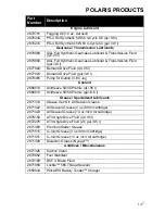
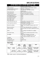
Page 148: ...allon 3 8 l Jug Coolant 2880514 Antifreeze 50 50 Premix qt 95 l 2880513 Antifreeze 50 50 Premix gal 3 8 l Grease Specialized Lubricants 2871312 Grease Gun Kit All Season Grease 2871322 All Season Grea...

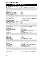
Page 149: ...rall Length 228 cm Overall Width 123 cm Overall Height 141 cm with mirrors installed Wheelbase 134 6 cm Ground Clearance 29 5 cm Minimum Turning Radius 213 cm unloaded Fuel System Bosch Multi Port Seq...

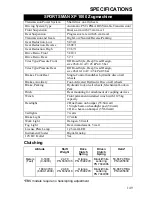
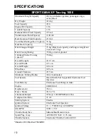
Page 150: ...ar Single Control handlebar hydraulic disc on all wheels Brakes Auxiliary Foot Activated Hydraulic Disc on all wheels Brake Parking Hydraulic lock on all wheels Mechanical Lock in Park Hitch Rear moun...

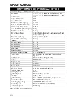
Page 151: ...g on level ground Unbraked Trailer Towing Capacity 868 kg Overall Length 211 cm Overall Width 121 cm Overall Height 129 cm Wheelbase 134 6 cm Ground Clearance 29 5 cm Minimum Turning Radius 213 cm unl...

Page 152: ...sure Rear Off Road Style Deep Tread Design size 26x10 14 AT 45 kPa Brakes Front Rear Single Control handlebar hydraulic disc on all wheels Brakes Auxiliary Foot Activated Hydraulic Disc on all wheels...

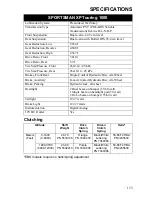
Page 153: ...ing Rating 750 kg on level ground Unbraked Trailer Towing Capacity 750 kg Overall Length 219 7 cm Overall Width 121 cm Overall Height 148 cm Wheelbase 145 cm Ground Clearance 29 5 cm Minimum Turning R...

Page 154: ...Size Pressure Rear 26x10 14 45 kPa Brakes Front Rear Single Control Hydraulic Disc All Wheel Brake Auxiliary Foot Activated Hydraulic Disc All Wheel Brake Parking Hydraulic lock all wheel Headlight 2...

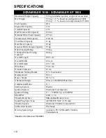
Page 155: ...e Capacity 75 kg Hitch Towing Rating 750 kg Unbraked Trailer Towing Capacity 868 kg Overall Length 209 5 cm Overall Width 122 cm Overall Height 125 7 cm Wheelbase 134 6 cm Ground Clearance 27 cm Minim...

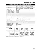
Page 156: ...Front 26x8 14 35 kPa Tires Pressure Rear 26x10 14 35 kPa Hand Brake Single Control Hydraulic Disc All Wheel Foot Brake Foot Activated Hydraulic Disc All Wheel Brake Parking Hydraulic Lock All Wheel Me...

Page 157: ...nal registration and received the customer copy please contact your dealer immediately NO WARRANTY COVERAGE WILL BE ALLOWED UNLESS YOUR VEHICLE IS REGISTERED WITH POLARIS Initial dealer preparation an...

Page 158: ...S AVAILABLE TO ANY PERSON FOR BREACH OF THIS WARRANTY POLARIS SHALL HAVE NO LIABILITY TO ANY PERSON FOR INCIDENTAL CONSEQUENTIAL OR SPECIAL DAMAGES OF ANY DESCRIPTION WHETHER ARISING OUT OF EXPRESS OR...

Page 159: ...s vary considerably from country to country You may be required to present documentation of your move to POLARIS in order to continue your warranty coverage You may also be required to obtain document...

Page 160: ...assignment outside of the country where the product was purchased will continue to be covered by the Limited Warranty Please work with your dealer to resolve any warranty issues Should your dealer req...

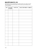
Page 161: ...section of your manual to your dealer each time your vehicle is serviced This will provide you and future owners with an accurate log of maintenance and services performed DATE MILES KM OR HOURS TECHN...

Page 162: ...161 MAINTENANCE LOG DATE MILES KM OR HOURS TECHNICIAN SERVICE PERFORMED COMMENTS...

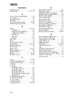
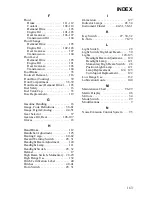
Page 163: ...ortsman XP Touring 1000 153 Zugmachine 149 Cold Weather Operation 65 Compartment Front 38 39 Coolant Bottle 109 Coolant Radiator 110 Cooling System 108 110 D Demand Drive Fluid 105 Diagnostic Codes 58...

Page 164: ...loves 18 H Hand Brake 112 Handlebar Adjustment 125 Hauling Cargo 80 82 Hazard Warning Switch 28 31 Headlight Beam Adjustment 120 Headlight Lamp 121 Headlight Switch 28 32 Helmet 17 High Beam Switch Mo...

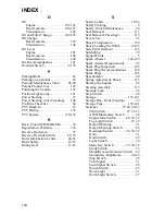
Page 165: ...8 Safety Winch Maintenance 94 Seat Removal 115 Seat Removal Passenger 115 Severe Use 96 Shock Compression 124 Shock Loading the Winch 92 93 Side Panel Removal 116 Sidehilling 76 Signal Words 5 Spark...

Page 166: ...le 142 Turn Signal Lamp Replacement 122 Turn Signal Replacement Front 122 Turn Signal Switch 28 31 Turning Around on a Hill 78 79 Turning the Vehicle 67 V Vehicle Identification Numbers 7 Vehicle Imme...

Page 167: ...For your nearest Polaris dealer visit www polaris com Polaris Sales Europe Sarl Route de l Etraz Business Center A5 1180 Rolle Switzerland Part No 9927460 Rev 01...

Reviews: