background image

ENGINE

2.43

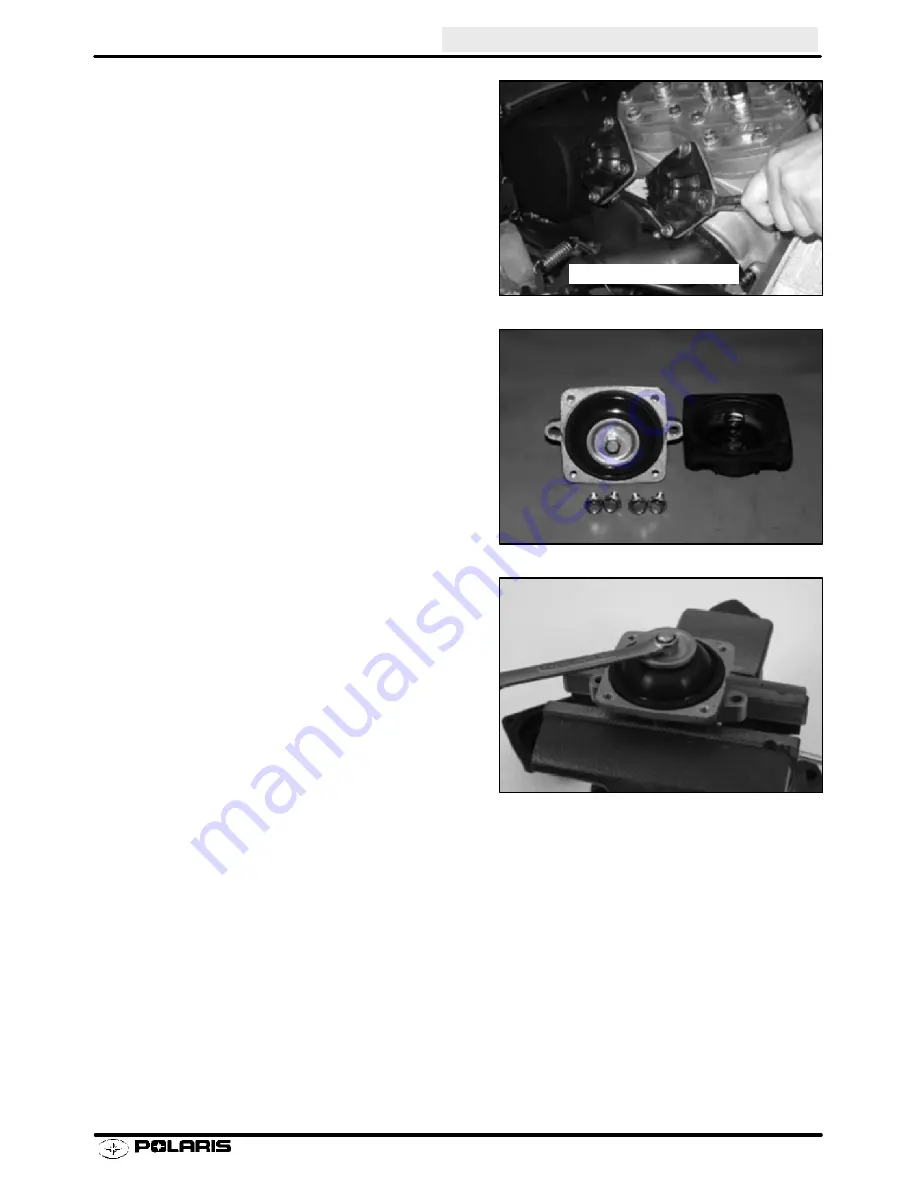
V.E.S. Removal

1.

Remove the mounting bolts.

On Domestic Engines remove all four (4) mounting bolts
and be ready to catch the spring and cover as you remove
the mounting bolts.

CAUTION:

Valve is spring loaded. Hold cover in position

until all bolts are removed.

2.

Remove exhaust valve assembly from the cylinder(s).

3.

800 Fuji engines, remove four cover bolts, cover, and
return spring.

CAUTION:

Valve is spring loaded. Hold cover in position

until bolts are removed.

4.

If the spring stays in the cover, hold the cover with
spring facing toward you. Rotate spring in a
counterclockwise direction while pulling outward on the
spring. Do not distort the spring upon removal.

5.

Insert V.E.S. in a soft jawed vice. Carefully remove
exhaust valve cap.

NOTE:

Top nut is secured to valve with adhesive. Remov-

ing top nut may damage threads on valve. If nut will not
loosen, apply a small amount of heat to cap. DO NOT
OVERHEAT or damage to the bellows will result.

Domestic Twin Engines

Enfocus Software - Customer Support

Summary of Contents for 2003 Pro X

Page 1: ......

Page 2: ...l riding position This manual includes procedures for maintenance operations component identification and unit repair along with service specifications for the 440 PRO X Fan 440 PRO X 600 PRO X 700 PRO X 800 PRO X Polaris snowmobiles A table of contents is placed at the beginning of each chapter and an alphabetic index is provided at the end of the manual for location of specific page numbers and ...

Page 3: ...ecautions that must be taken to avoid personal injury or snowmobile or prop erty damage NOTE A NOTE provides key information to clarify instructions Trademarks Polaris acknowledges the following products mentioned in this manual FLEXLOC Registered Trademark of SPS Technologies Loctite Registered Trademark of the Loctite Corporation STA BIL Registered Trademark of Gold Eagle FOX Registered Trademar...

Page 4: ... areas of information Keep this manual available for reference In order to provide you with the best support possible Polaris racing engineering and testing department personnel must have timely and accurate data from the field The weekly racing report form is a valuable source of this data As a part of the Polaris team your input is highly valued and never ignored At Polaris we are committed to y...

Page 5: ......

Page 6: ... Specifications 440 PRO X Fan 1 4 1 5 440 PRO X 1 6 1 7 600 PRO X 1 8 1 9 700 PRO X 1 10 1 11 800 PRO X 1 12 1 13 Bolt Size Guide 1 14 Decimal Equivalent Chart 1 15 Conversion Table 1 16 Tap Drill Charts 1 17 Glossary of Terms 1 18 1 21 Tool List 1 22 Recommended Maintenance Products 1 23 ...

Page 7: ... the performance of your machine will be at its peak 1 Always break in any new part for 50 75 miles before using it for racing 2 Clutch springs and belts need to be broken in to reach their peak in performance 3 On the 440 Pro X always use the correct type of fuel for the timing system you are using 4 Pre mix 20 1 on break in and 32 1 after break in on the 440 Pro X liquid only 5 Always use the re...

Page 8: ... 5411465 Thermostat Gasket PN 5830113 and clutch weights for use at 0 3000 ft 3 PN 1321730 Please follow the instructions clutching and jetting recommendations included in the kit Jets are not included in this kit and are not warrantable Please install this Head Kit PN 2202188 on all 440 Pro X Liquid mod els that will be used for trail riding The installation of this kit must be performed by an au...

Page 9: ...ce Manuals 2000 2003 120 XC SP 9918046 Trail Sport Super Sport 340 EDGE 340 Classic 500 440 PRO X FAN 9918048 Touring Wide Trak LX 340 Touring Sport Touring Trail Touring 500 Classic Touring 600 Classic Touring 700 Classic Touring 9918047 Frontier Frontier Classic Frontier Touring 9918050 Trail Luxury 340 Classic EDGE 500 Classic 550 Classic 600 Classic 700 Classic 9918049 Deep Snow Trail RMK 600 ...

Page 10: ...eters 0 900 S 55 H Almond Silver R49 21 41 74P Meters Feet 0 900 0 3000 S 55 H Almond Red Silver Blue R49 3 21 41 74P HYVO 900 1800 S 53 H Almond Silver R49 21 41 74 P 900 1800 3000 6000 S 53 H Almond Red Silver Blue R49 3 21 41 74 P HYVO 1800 2700 10 AL Almond Silver R49 21 41 74 P 1800 2700 6000 9000 10 AL Almond Red Silver Blue R49 4 21 41 74 P HYVO 2700 3700 10 Almond Silver R49 21 41 74 P 270...

Page 11: ...erse Option IFS Shocks Ryde FXt Brake Pads HayesType 81 IFS Spring Rate 90 180 in Chaincase Center Dist 7 92 20 12cm Front Spring Preload 2 8s Thread Adjust Driveshaft Sprockets 2 Drivers Front Vertical Travel 9 22s 23 4 cm Brake Type Polaris HPB Rear Suspension Pro X Rear Travel 13 9s 35 3 cm Front Track Shock Ryde FX t Spring Rate 190 in Rear Track Shock Ryde FXt IFP Clicker Rear Springs 347s 77...

Page 12: ...mond Red 140 200 Red Blue 70 44 46 19 43 74P 900 1800 S 49H Almond 140 200 70 44 19 43 900 1800 3000 6000 S 49H Almond Red 140 200 Red Blue 70 44 46 19 43 74P 1800 2700 S 47H Almond 140 200 70 44 19 43 1800 2700 6000 9000 S 47H Almond Red 140 200 Red Blue 70 44 46 19 43 74P 2700 3600 S 45H Almond 140 200 62 40 19 43 2700 3600 9000 12000 S 45H Almond Red 140 200 Red Blue 62 40 46 19 43 74P ENGINE T...

Page 13: ...vans Alum IFP Brake Pads Hayes Type 81 Comp Adjust w Res Chaincase Center Dist 7 92 20 12cm IFS Spring Rate 74 165 in Driveshaft Sprockets 2 Drivers wide Front Spring Preload 3 75s Thread Adjust Brake Type Hayes Front Vertical Travel 9 22s 23 42 cm Rear Suspension PRO X Rear Travel 13 90s 35 31 cm Front Track Shock Walker Evans Alum IFP Comp Adjust w Res Spring Rate 160 in Rear Track Shock Walker ...

Page 14: ... 46 23 39 74P HYVO 1800 2700 10 54 Dark Blue Red Dark 58 40 22 39 74P 1800 2700 6000 9000 10 54 Dark Blue White Red Dark Blue 58 40 46 22 39 74P HYVO 2700 3700 10 Dark Blue Red Dark 58 40 22 40 74P 2700 3700 9000 12000 10 Dark Blue White Red Dark Blue 58 40 46 22 40 74P HYVO Production Setting ENGINE Type Liquid Cooled Case Reed w VES Displacement 593cc Fuel Pump Manuf N A Bore 3 041s 77 25mm Fuel...

Page 15: ...pe 81 IFS Spring Rate 90 180 in Chaincase Center Dist 7 92s 20 12cm Front Spring Preload 2 75s Thread Adjust Driveshaft Sprockets 2 Drivers Wide Front Vertical Travel 9 22s 23 4cm Brake Type Polaris HPB Liquid Cooled Rear Suspension PRO Xt Rear Axle Travel 13 86 35 2cm Front Track Shock Ryde FX IFP w R R Spring Rate 160 Rear Track Shock Ryde Fx IFP R R Preload 1 75 Rear Torsion Springs 359s sq 77q...

Page 16: ...800 2700 10 58 Black Black 62 40 23 39 74P 1800 2700 6000 9000 10 58 Black Green Black Red 62 40 46 23 39 74P HYVO 2700 3700 10 56 Black Black 62 40 23 39 74P 2700 3700 9000 12000 10 56 Black Green Black Red 62 40 46 23 39 74P HYVO Production Setting ENGINE Type Liquid Cooled Case Reed Twin Displacement 701cc Fuel Pump Manuf N A Bore 3 1889s 81mm Fuel Pump Mark N A Stroke 2 6772s 68mm Oil Pump Man...

Page 17: ...ring Rate 90 180 in Chaincase Center Dist 7 92s 20 12cm Front Spring Preload 2 75s Thread Adjust Driveshaft Sprockets 2 Drivers Wide Front Vertical Travel 9 22s 23 4cm Brake Type Polaris HPB Liquid Cooled Rear Suspension PRO Xt Rear Axle Travel 13 86 35 2cm Front Track Shock Ryde FX IFP w R R Preload 1 75 Spring Rate 160 Rear Track Shock Ryde Fx IFP R R Rear Torsion Springs 359s sq 77q Track Type ...

Page 18: ...Red 62 44 23 39 74P 1800 2700 6000 9000 10 60 Black Green Black Red 62 44 46 23 39 74P HYVO 2700 3700 10 58 Bl ck ree Bl ck Red 62 44 23 39 74P 2700 3700 9000 12000 10 58 Black Green Black Red 62 44 46 23 39 74P HYVO Production Setting ENGINE Type Liquid Cooled Case Reed Twin Fuel Pump Manuf N A Displacement 794cc Fuel Pump Mark N A Bore 3 3464s 85mm Oil Pump Manuf Mikuni Stroke 2 7559s 70mm Oil P...

Page 19: ...ring Rate 90 180 in Chaincase Center Dist 7 92s 20 12cm Front Spring Preload 2 75s Thread Adjust Driveshaft Sprockets 2 Drivers Wide Front Vertical Travel 9 22s 23 4cm Brake Type Polaris HPB Liquid Cooled Rear Suspension PRO Xt Rear Axle Travel 13 86 35 2cm Front Track Shock Ryde FX IFP w R R Preload 1 75 Spring Rate 160 Rear Track Shock Ryde Fx IFP R R Rear Torsion Springs 359s sq 77q Track Type ...

Page 20: ... lbs Nm 1 4 20 5 7 8 11 12 16 1 4 28 6 8 10 14 14 19 5 16 18 11 15 17 23 25 35 5 16 24 12 16 19 26 29 40 3 8 16 20 27 30 40 45 62 3 8 24 23 32 35 48 50 69 7 16 14 30 40 50 69 70 97 7 16 20 35 48 55 76 80 110 1 2 13 50 69 75 104 110 152 1 2 20 55 76 90 124 120 166 To convert ft lbs to Nm multiply foot pounds by 1 382 To convert Nm to ft lbs multiply Nm by 7376 ...

Page 21: ...7s 13 32 4063 27 64 4219 11 mm 4331s 7 16 4375 29 64 4531 15 32 4688 12 mm 4724s 31 64 4844 1 2 5 13 mm 5118 33 64 5156 17 32 5313 35 64 5469 14 mm 5512s 9 16 5625 37 64 5781 15 mm 5906s 19 32 5938 39 64 6094 5 8 625 16 mm 6299s 41 64 6406 21 32 6563 17 mm 6693s 43 64 6719 11 16 6875 45 64 7031 18 mm 7087s 23 32 7188 47 64 7344 19 mm 7480s 3 4 75 49 64 7656 25 32 7813 20 mm 7874s 51 64 7969 13 16 ...

Page 22: ... in Imperial pints Imp pt x 0 568 Liters l Liters l x 1 76 Imperial pints Imp pt Imperial quarts Imp qt x 1 137 Liters l Liters l x 0 88 Imperial quarts Imp qt Imperial quarts Imp qt x 1 201 US quarts US qt US quarts US qt x 0 833 Imperial quarts Imp qt US quarts US qt x 0 946 Liters l Liters l x 1 057 US quarts US qt US gallons US gal x 3 785 Liters l Liters l x 0 264 US gallons US gal Pounds for...

Page 23: ... 64 1 1 8 12 1 3 64 1 1 4 7 1 7 64 1 1 4 12 1 11 64 1 1 2 6 1 11 32 1 1 2 12 1 27 64 1 3 4 5 1 9 16 1 3 4 12 1 43 64 2 4 1 2 1 25 32 2 12 1 59 64 2 1 4 4 1 2 2 1 32 2 1 2 4 2 1 4 2 3 4 4 2 1 2 3 4 2 3 4 Metric Tap Drill Sizes Tap Size Drill Size Decimal Equivalent Nearest Fraction 3 x 50 3 x 60 4 x 70 4 x 75 5 x 80 5 x 90 6 x 1 00 7 x 1 00 8 x 1 00 8 x 1 25 9 x 1 00 9 x 1 25 10 x 1 25 10 x 1 50 11...

Page 24: ... it Combustion Chamber Space between cylinder head and piston dome at TDC Compression Reduction in volume or squeezing of a gas Condenser Capacitor A storage reservoir for electricity used in both E T and CDI systems Crankshaft Run Out Run out or bend of crankshaft measured with a dial indicator while crankshaft is supported between centers on V blocks or resting in lower half of crankcase Measure...

Page 25: ...rams per square centimeter Metric equivalent of PSI Keystone Ring A piston ring with bevel on upper inside surface Kilogram meter A force of one kilogram at the end of a lever one meter in length applied in a rotational direction Metric equivalent of ft lbs L Ring A wide face piston ring with an L shaped cross section Leg of L goes up when installing on piston Labyrinth Seal A pressure type center...

Page 26: ... this head Running Time Ignition timing when fully advanced or at specified RPM Secondary Circuit This circuit consists of the large secondarycoil windings high tensionwire andground throughthe spark plug air gap Secondary Clutch Driven clutch on chaincase or jackshaft Seized Piston Galling of the sides of a piston Usually there is a transfer of aluminum from the piston onto the cylinder wall Poss...

Page 27: ...ers in their holes and hand tighten Then following the method and sequence indicated in this manual tighten evenly to the specified torque value When removing nuts bolts or screws from a part with several fasteners loosen them all about 1 4 turn before removing them If the condition of any gasket or O Ring is in question replace it with a new one Be sure the mating surfaces around the gasket are c...

Page 28: ...as Fill Tool Gauge PS 45259 1 Gas Fill Needles 20 Pack PS 45260 Lower Retainer Wrench PS 45261 IFP Positioning Extraction Tool PS 45262 Cylinder Head Wrench PS 45263 Wear Band Tool PS 45152 THIN Rear Suspension Wrench PS 45909 High Performance Driven Clutch Compression Tool PS 45908 T Handle Walker Evans IFP Tool PS 45629 Body Clamps for Walker Evans 1 3 4 2871358 Clutch Holding Fixture 9314177 A ...

Page 29: ...eak in Lube 2 5 Gal 2 2871958 Silicone Black RTV 11 oz Cartridge 12 2871326 Carbon Clean Plus 12 oz 12 2871959 Ultra Blue RTV 3 35 oz 12 2871280 Premium Chaincase Lubricant Quart 12 2871960 Ultra Blue RTV 13 oz Cartridge 12 2870464 Premium Chaincase Lubricant Gallon 4 2871961 518 Flange Sealant 50cc 10 2872281 Premium Chaincase Lubricant 2 5 Gallon 2 CRANKCASE SEALANTS 2872951 Synthetic Chaincase ...

Page 30: ......

Page 31: ...27 2 32 700 800 Pro X Engine Dissassembly 2 33 2 38 700 800 Pro X Engine Assembly 2 38 2 42 VES Maintenance Adjustment 2 43 2 45 VES Optional Springs 2 46 General Inspection Procedures 2 47 2 49 Crankshaft Truing 2 50 2 51 Crankshaft Indexing 2 52 Exhaust Gas Tempurature 2 53 Piston Wash Spark Plug Color 2 54 Cylinder Head Inspection 2 55 Piston Inspection Measurement 2 56 Oil Pump Operation Inspe...

Page 32: ......

Page 33: ...2 520 2 Liquid 110 600 Pro X S2392 6044PA6E 593 77 25 3 041 64 2 520 2 Liquid 87 700 Pro X S2378 7070PA7C 701 81 3 189 68 2 677 2 Liquid 87 800 Pro X S2398 8070P8C 794 85 3 346 70 2 756 2 Liquid 87 Non oxygenated Use minimum 89 octane when using oxygenated fuel 110 Octane minimum Model Piston Cylinder Bore Clearance 05 mm 00 mm MM Inch Engine Operating RPM 200 Recommended Idle RPM 440 Pro X Fan 07...

Page 34: ...entimeters cm or meters m The most common units of torque in the English system are ft lb and in lb In the Metric system torque is commonly expressed in units of Nm Multiply foot pounds by 1 382 to obtain Nm See page 2 3 for engine torque sequences Engine Cylinder Head Cylinder Base Nuts Crankcase 8 mm Crankcase 10 mm Flywheel EC 45 18 19 ft lbs 25 26 5 Nm 24 28 ft lbs 33 39 Nm 17 18 ft lbs 22 23 ...

Page 35: ... 6 2 3 7 11 CRANKCASE 440 600 Pro X 15 14 13 CYLINDER BASE 440 600 Pro X 3 1 6 4 2 5 CYLINDER HEAD Pro X Fan 9 5 1 3 7 11 10 6 2 4 8 12 CRANKCASE Pro X Fan 5 1 7 3 9 2 11 4 10 6 12 8 CYLINDER HEAD Libertyt 700 800 3 2 4 1 5 6 7 8 CYLINDER BASE Libertyt 700 800 Libertyt Crankcase 700 800 5 4 2 1 3 6 ...

Page 36: ...p IHV Eff Disp IHV Effective Compression Ratio Eff Comp 6 725 In order to increase the Full Stroke Compression Ratio to 13 6 how much material do you need to remove from the cylinder head R IHV Displacement IHV You know that and you want to find out IHV Displacement 199 098 cc and we want R 13 6 so then IHV2 Displacement R 1 IHV2 15 801 cc desired IHV to have 13 6 1 Full Stroke Compression Ratio I...

Page 37: ...eed to remove by the number of inches to remove per CC Thickness to remove I ô Removed CCs Thickness to remove 0 015 in Port open 81 5q This indicates the degrees after TDC that the exhaust port opens and also the degrees before TDC that the port closes Duration closed 2 ô Port open Duration closed 163q Total duration 360q Duration open Total duration Duration closed Duration open 197q Percent ope...

Page 38: ...uce as much peak horsepower for a given displacement range In general an engine designed for a racing or high performance snowmobile will have a relatively high exhaust port compared to an engine of the same displacement range designed for touring Although the V E S does not in itself increase horsepower it does allow an engine to be designed for maximum horse power without the inherent disadvanta...

Page 39: ... Removal and cleaning is covered later in this chapter V E S Troubleshooting Symptom Possible Cause Remedy Engine will not reach designed operating RPM Valve not opening or not opening completely 1 Exhaust valve sticking 2 Cylinder pressure feed port restricted 3 Bellows damaged or not sealing correctly 4 Incorrect spring 5 Problem in clutch setup drive line engine etc 1 Remove carbon deposits bur...

Page 40: ...his time the exhaust valves are down When the CDI senses 6700 RPM it triggers the solenoids to shut off the bypassed air going to the atmosphere Pressure then builds inside the exhaust valve bellows causing the valves to fully open When RPM drops below 6700 the solenoids open to allow air to bypass through to atmosphere and the exhaust valves close CDI Box Solenoid Closed Solenoid Closed Wire Wire...

Page 41: ...pe and the racing conditions which may vary depending on the race The standard position is D and should not be moved unless you are a knowledgeable engine tuner Position Timing Effect A 3 B 2 C 1 D Standard Position 0 E 2 F 3 G 4 This engine is jetted for operation at 0 degrees _F and warmer Re jetting is required for temperatures colder than 0_F CAUTION ...

Page 42: ...uring disassembly Replace all seals O rings and gaskets with Genuine Polaris parts during assembly Disassembly 1 Remove coil pack from air box and disconnect it from the wiring harness 2 Loosen carburetor clamps and remove each carburetor 3 Using a pliers detach the oil lines from the carburetors ...

Page 43: ... the carburetor mounting boots using a allen wrench 5 Remove both the cylinder head and exhaust side fan shroud s from the engine assembly 6 After removing the fan shrouds take note of the vibration dampener located between the two intake ports ...

Page 44: ...emove the CDI module from the flywheel cover 8 Remove the flywheel cover 9 Prior to removing the flywheel insert a piece of nylon rope or cord into a spark plug hole Rotate the crankshaft counter clockwise until it will no longer turn over ...

Page 45: ...ve the recoil cam 11 Loosen and remove the flywheel nut 12 Using a flywheel puller remove the flywheel from the engine Do not install puller bolts more than 5 16s 7mm into flywheel threads or stator damage may result Flywheel Puller PN 2871043 ...

Page 46: ...ENGINE 2 14 Disassembly Continued 13 Remove the flywheel 14 The stator plate can be removed without taking off the stator 15 Remove the oil pump taking note of the o ring and shim s ...

Page 47: ...ENGINE 2 15 Disassembly Continued 16 Remove the cylinder head 17 Remove the head gasket During removal note that the head gasket is stamped with EX and UP 18 Loosen and remove each cylinder ...

Page 48: ...ler remove the pistons CAUTION Wear eye protection during piston c clip removal to prevent eye injury 21 Turn crankcase over and remove the crankcase bolts Turn over and separate the case halves 22 Refer to General Inspection section for crankshaft inspection and measurement procedures Piston Pin Puller PN 2870386 ...

Page 49: ...mbly 1 Prior to assembly make sure that you have all of the oil pump shims when the oil pump was removed and that the shims are installed in the correct order 2 Insert oil pump drive gear 3 Insert oil pump driveshaft spacer 4 ...

Page 50: ...ation pins rest in their appropriate galleries NOTE Lubricate the crankseal prior to installation 6 Apply 3 Bond sealer to top half of crankcase Lubricate oil pump drive gear 7 Install the upper case half 8 Turn the crankcase over and torque the case bolts in sequence illustrated in beginning of chapter 3 Bond 1215 PN 2871557 120 Gram Tube Crankcase Bolt Torque 16 6 18 ft lbs 22 25 Nm ...

Page 51: ...be facing with the open end up 10 Lubricate rings and pistons with two stroke oil Install rings with letter mark or beveled side facing upward 11 Install the reed valves in the crankcase After installing the reed valves insert the base gaskets 12 Install each cylinder Torque cylinder base nuts in sequence illustrated in beginning of chapter Cylinder Base Nut Torque 24 28 ft lbs 33 39 Nm ...

Page 52: ...the cylinder head gasket with the EX on the exhaust side and UP on the intake side of the engine 14 Insert the dowels into the flywheel housing NOTE Refer to picture for proper installation of alignment dowels 15 Tighten flywheel housing to crankcase ...

Page 53: ...wheel and insert the lock washer 17 Torque the flywheel nut During the procedure use a flywheel holding wrench to prevent the flywheel from rotating 18 Reinstall the flywheel cover Flywheel Holding Wrench PN 8700229 Flywheel Nut Torque 60 65 ft lbs 83 90 Nm ...

Page 54: ... intake ports Reinstall the two fan shrouds making sure that they interlock before fastening tightly 20 Using a new o ring reinstall the oil pump 21 Install each carburetor and torque the carburetor mounting clamps Reinstall oil lines on the oil pump Oil Pump Mounting Screw Torque 48 72 in lbs 5 5 8 3 Nm ...

Page 55: ...ir gap between fiber reed and reed block as shown The air gap should not exceed 015s 4 mm If clearance is excessive DO NOT attempt to reverse the reeds to reduce the air gap Always replace them if damaged Check each fiber reed for white stress marks or missing material Replace if necessary 2 Remove V E S if applicable 3 Remove cylinder head cover and inspect O rings and sealing surfaces for damage...

Page 56: ...g pistons and connecting rods to prevent piston damage Refer to General Inspection Procedures in this chapter 6 Remove outer piston pin C clips using a scribe through access slot in piston 7 Place support block under piston and remove piston pins using pin puller 8 Remove water pump cover from front of engine Piston Pin Puller PN 2870386 Support Block PN 2870390 ...

Page 57: ...eel puller Use drive clutch puller T handle or a wrench to hold puller 11 Before removing stator plate note where ignition timing marks are located or scribe additional marks for reference upon reassembly 12 Mark or note location of engine mount straps and remove Flywheel Puller PN 2871043 T Handle PN 5020326 ...

Page 58: ...e to snap ring grooves lift crankshaft straight upward and out of lower case 15 Tap out the drive shaft using a center punch and hammer Locate the center punch in the centering hole on the oil pump end of the shaft Be careful not to damage the bearing This will remove the oil seal and the mechanical seal from the crankcase ...

Page 59: ...he retaining pin hole as a guide carefully drill a hole in the new bushing to the same depth and di ameter as the hole in the old bushing Be careful not to enlarge the retaining pin hole or drill too deep S Install new retaining pin 4 Lubricate and install oil seal with seal lip out towards you until it is against the bushing 5 Lubricate and install new mechanical seal using the Mechanical Seal Gu...

Page 60: ...ly Pack the crankcase PTO end cavity with 22 grams of Mobile 1 Synthetic grease 12 Install seals on crankshaft with spring facing inward toward crankshaft 13 Clean and de grease lower crankcase and install crankshaft assembly aligning seals and snap ring with grooves in case 14 Apply a thin coating of 3 Bond 1215 sealant to lower crankcase mating surface 15 Install upper crankcase on lower crankca...

Page 61: ...ew base gasket Be sure gasket surface is clean and free of nicks burrs or scratches 24 Lubricate and install piston rings on piston withmark on end of ring facing upward 25 Place piston support under skirt and lubricate pistons and cylinders thoroughly 26 Align ring end gaps with locating pins and compress rings Install cylinder carefully with a gentle front to rear rocking motion Install cylinder...

Page 62: ...stall 30 Torque head bolts to specification outlined on page 2 3 of this chapter 31 Torque cylinder base nuts outlined on page 2 3 2 4 of this chapter 32 Install washers and water pump impeller as shown and torque nut to 10 ft lbs 14 Nm CYLINDER HEAD 440 Pro X 1 4 2 6 3 8 5 10 7 11 9 12 3 2 4 1 5 6 7 8 CYLINDER BASE 440 Pro X PTO SIDE MAG SIDE Washer 10 3x14x1mm 10 ft lbs 14 Nm Washer 325x 75x 063...

Page 63: ... adaptor bolt 37 Install stator assembly aligning timing marks or marks made upon disassembly Seal stator wires with high temperature silicone sealant Install and tighten stator screws to specification 38 Measure trigger pulse coil gap and compare to specification Water Pump Cover Bolt Torque 9 Ft lbs 12 5 Nm Exhaust Manifold Bolt Torque 16 Ft lbs 22 Nm Seal Stator Wires Apply Loctitet 262 to Tape...

Page 64: ... Use flywheel holder to hold flywheel and torque nut to specification found in beginning of this chapter 42 Install recoil hub and recoil housing Torque bolts to specification 43 Install engine in chassis and align clutches 44 Refer to General Inspection Procedures in this chapter to fill and bleed cooling system and oil pump Flywheel Holder PN 8700229 Recoil Hub and Housing Bolt Torque 108 in lbs...

Page 65: ...hapter Disassembly 1 Remove the oil pump 2 Remove the recoil housing and the recoil hub Inspect waterpump drive belt for missing cracked or broken drive cogs Measure the belt at 4 different points as shown Re place if width is less than 250s 6 35mm Nominal new width is 345s 8 75mm 3 Remove drive gears and belt 4 Remove flywheel nut using flywheel holder Replace if width is less than 25s 6 35mm Fly...

Page 66: ...he ignition timing strip on the flywheel 7 Before removing stator plate mark the plate and crankcase for reference upon assembly 8 Remove bolts holding water pump housing to crankcase Loosen hose clamp and remove housing Flywheel Puller PN 2871043 Timing strip Hose Clamp 1 2 3 4 ...

Page 67: ...eplace if necessary Replace mechanical seal using the special tools listed below Use the seal press to install a new mechanical seal in cover with spring sleeve toward impeller housing Install seal guide over end of shaft and apply a light film of grease to seal guide Carefully install shaft and bearings in cover Assemble 10x14mm washer impeller washer and nut Torque impeller nut to 10 ft lbs 14Nm...

Page 68: ...attempt to reverse the reeds to reduce the air gap Always replace them if damaged Check each fiber reed for white stress marks or missing material Replace if necessary 15 Remove V E S assembly Clean valves as outlined later in this chapter 16 Remove cylinder head Note condition and placement of cylinder head O rings 17 Loosen cylinder base nuts and remove cylinders Max Reed Pedal Clearance 015s 38...

Page 69: ...g piston pin in place 19 Remove piston pin using piston pin puller and adaptor 20 Remove water manifold by removing both retainer brackets 21 Remove bottom crankcase bolts and separate crankcase halves Piston Pin Puller PN 2870386 Adaptor PN 5130971 Remove Clamps ...

Page 70: ...15 sealant to upper crankcase half NOTE Use only 3 Bond 1215 sealant Curing time and film thickness are critical for proper bearing clear ance 3 Set crankshaft in lower crankcase Lubricate seal lips with Premium All Season Grease Make sure seals are positioned properly with lip and spring facing inward toward crankshaft Install snap rings with gap facing upward toward upper case half 3 Bond 1215 P...

Page 71: ...to specification in the proper sequence found in the beginning of this chapter 7 Install new O rings on water manifold Grease O rings and install manifold 8 Lubricate main bearing oil holes with Polaris Premium 2 Cycle or Premium Gold engine oil and rotate crankshaft to distribute oil evenly 9 Install a new C clip in both pistons inside with gap facing up or down Be sure clip is fully seated in th...

Page 72: ...g and cylinders with two stroke oil and install cylinders Align ring end gaps with locating pins and compress rings Install cylinder carefully with a gentle front to rear rocking motion Loosely install the cylinder nuts 14 Install new cylinder head O ring and install cylinder head Make sure O ring is properly seated in groove 15 Torque cylinder base bolts in proper sequence Refer to specifications...

Page 73: ...ump housing from inside toward outside until bottomed on housing Spring and seal lip must face inward toward crankshaft 19 Apply 3 Bond sealant to pump housing crankcase mating surface and carefully install onto crankcase Tighten water pump to engine hose clamp and torque bolts to specification 1 2 3 4 5 6 7 8 9 10 11 12 Install Seal Apply 3 Bond Hose Clamp 1 2 3 4 Ignition Water Pump Housing Torq...

Page 74: ...and recoil hub NOTE See domestic twin water pump belt installation in chapter 2 Maintenance for correct belt installation 23 Install recoil cover and oil pump Make sure oil pump drive slot mates properly with water pump shaft 24 Install reed valve reed stuffer and reed cover Flywheel Nut Torque 90ft lbs 124 Nm Recoil Hub Bolt Torque 96 108 in lbs 11 12 5 Nm ...

Page 75: ...ring CAUTION Valve is spring loaded Hold cover in position until bolts are removed 4 If the spring stays in the cover hold the cover with spring facing toward you Rotate spring in a counterclockwise direction while pulling outward on the spring Do not distort the spring upon removal 5 Insert V E S in a soft jawed vice Carefully remove exhaust valve cap NOTE Top nut is secured to valve with adhesiv...

Page 76: ...its can be removed from valve with a Scotch Britet pad or similar soft abra sive brush 5 Lubricate exhaust valve with Polaris Premium Gold 2 cycle engine lubricant Install valve in cylinder and move it through the entire travel range to check for free movement without bind ing If the valve sticks anywhere in the travel range check the valve and valve bore in the cyl inder for carbon deposits and c...

Page 77: ...cation 4 Install spring valve cover and adjuster nut Torque exhaust valve cover bolts to specifica tion 5 Install V E S assembly onto cylinder and torque V E S housing bolts to specification Domestic Engines utilize two of the cover bolts for mount ing to the cylinder The torque value for these are 12 ft lbs 16Nm Valve Cap Torque 6 Ft lbs 8 3 Nm Fuji Valve Cover Bolt Torque 4 Ft lbs 5 5 Nm Domesti...

Page 78: ...49 7041786 09 RED YELLOW 3 0 3 7 2 586 037 7041786 11 PINK YELLOW 9 0 11 5 2 323 051 7041704 01 BLUE 4 0 6 0 1 752 0475 7041704 02 ORANGE 5 5 8 3 1 729 0475 7041704 03 PINK 4 7 7 1 1 734 046 7041704 04 PURPLE 3 1 4 7 1 726 040 7041704 05 YELLOW 2 4 3 6 1 734 037 7041704 06 WHITE 1 6 2 8 1 537 036 These springs will change the timing characteristics of the exhaust valve opening A heavier spring wil...

Page 79: ...shatch is too steep oil retention will be reduced A cross hatch angle which is too shallow will cause ring vibration poor sealing and overheating of the rings due to blow by and reduced contact with the cylinder wall Service life of the pistons and rings will be greatly reduced Except Nicasil Cylinder Hone Selection Selecting a hone which will straighten as well as remove material from the cylinde...

Page 80: ... solvent then in hot soapy water Pay close attention to areas where the cylinder sleeve meets the alumi num casting transfer port area Use electrical contact cleaner if necessary to clean these areas Rinse thor oughly dry with compressed air and oil the bore immediately with Polaris Premium 2 Cycle Lubricant Crankcase Inspection Bearing Fit Any time crankshaft bearing failure occurs and the case i...

Page 81: ...eedle bearings if worn or cracked and always replace them if piston damage has occurred 3 Visually inspect piston pin for damage discoloration or wear Run your fingernail along the length of the pin and replace it if any rough spots galling or wear is detected Connecting Rod Small End Inspection 1 Clean small end of connecting rod and inspect inner bore with a magnifying glass Look for any surface...

Page 82: ...ously straightened areas to verify truing Refer to the illustrations below Crankshaft Runout Inspection When checking the crankshaft runout it is important to measure with a dial indicator in the correct position When measuring on the flywheel side SMeasure runout 1 2 12 7mm from the bearing flat When measuring from the PTO side SMeasure runout where the taper starts after the bearing flat Refer t...

Page 83: ... a situation like the one shown in the illustration at right squeeze the crankshaft at point A Use tool from alignment kit 7 If the crank rod pin location is 180_ from the dial indicator opposite that shown above it will be necessary to spread the crankshaft at the A position as shown in the illustration at right When rebuilding and straightening a crankshaft straightness is of utmost importance R...

Page 84: ...dicator installed 5 Locate TDC as accurately as possible by finding the center of the point where there is no piston movement Zero the dial indicator at this point Continue to rotate the crankshaft in the normal direction of rotation until the dial indicator reads 100s 2 54mm after top dead center ATDC IMPORTANT Do not allow the crankshaft to move from this position Crankshaft Indexing Continued 6...

Page 85: ...ATION 1150 1200_F 621 649_C NORMAL 1 Pipe Per Cylinder Above 1200_F 649_C DETONATION 1150 1200_F 621 649_C NORMAL 1 5 38mm NOTE The temperatures given are approximate and should only be used as an example You must determine the EGT numbers that are correct for your machine For more information contact Bill Rader 715 355 5157 ...

Page 86: ... below to help you establish the EGTs for your machine n If the wash is 1 4 3 8 and cocoa brown the machine s EGTs are just right n Wet and Black wash indicates too rich a fuel mixture n A dry ash colored piston indicates too lean a mixture for the operating conditions n If the plug is light to cocoa brown the machine s EGTs are just right n If the plug is wet or very dark the fuel is running too ...

Page 87: ...of round with a telescoping gauge or a dial bore gauge Measure the bore 1 2s from the top of the cylinder in line with the piston pin and 90q to the pin to determine if the bore is out of round Repeat the measurements at the middle and bottom of the cylinder to determine taper or out of round at the bottom Record all measurements Cylinder Head Warp Service Limit 003s 08mm Top Middle Bottom X X X Y...

Page 88: ...clearance exceeds the service limit the cylinder should be re bored and new pistons and rings installed Piston Ring Installed Gap 1 Position ring 1 2I 1 3 cm from the top of the cylinder using the piston to push it squarely into place Measure installed gap with a feeler gauge at both the top and bottom of the cylinder NOTE A difference in end gap indicates cylinder taper The cylinder should be mea...

Page 89: ...etors 3 Place oil feed lines with their check valves away from the clutch area Start the engine and let it idle at normal idle RPM 4 Lift oil pump control lever up to its maximum flow position 5 Drops of oil should be visible from the banjo check valves after the engine is idled one to two minutes with a drop occurring approximately every few seconds 6 If oil does not flow from one of the check va...

Page 90: ...ments have been made the oil pump must also be adjusted 1 With engine shut off and throttle in its idle position the pump lever index mark A must align with the pump housing boss index mark B 2 Loosen lock nuts on cable housing sleeve and vary cable housing length as required NOTE Verify that pump lever is actuated upon initial throttle opening Oil Pump Drive Gear End Play Adjustment If the oil pu...

Page 91: ...ubtract from total bushing end play determined in step 3 5 Add or subtract shims as required to provide specified end play 6 Lightly grease a new O ring and install it on the pump Install pump engaging slot in shaft with drive gear Apply Loctite 242 to bolts and torque evenly to 78 in lbs 9 Nm Measurement A Measurement B Oil Pump Mounting Bolt Torque 242 Blue 78 in lbs 9 Nm Optional Shims PN 30836...

Page 92: ...n system which may result in overheating Filling and Bleeding Procedure If the cooling system should become low in the reservoir tank and or filler neck the system should be bled of any trapped air using one of the following procedures depend ing on model 440 500 600 700 Domestic Twins Bleeding Pro cedure 1 Fill cooling system Leave pressure cap off 2 With engine running at specified idle speed lo...

Page 93: ...GINE 2 61 Cooling System 440 Pro X NOTE When leak testing cooling system system pressure should not exceed 2 lbs less than cap pres sure ENGINE COOLANT BOTTLE CENTER COOLER TUNNEL STRIP COOLERS 440 Pro X ...

Page 94: ...ENGINE 2 62 Cooling System 600 Pro X ENGINE COOLANT BOTTLE CENTER COOLER TUNNEL STRIP COOLERS 600 Pro X ...

Page 95: ...ENGINE 2 63 Cooling System 700 800 Pro X 700 800 PRO X ENGINE COOLANT BOTTLE CENTER COOLER TUNNEL STRIP COOLERS ...

Page 96: ...et Throttle slides not fully open Chain too tight Clutching Excessive driveline friction Hi Fax overheating Engine runs but fails to idle Incorrect air mixture setting Throttle stop screw incorrectly adjusted Dirt in pilot jet Low compression Tight belt Piston damage Chokes not seating Engine runs but overloads with fuel Chokes are not seating Fuel pump diaphragm is ruptured caused by engine backf...

Page 97: ...iew 3 7 Fuel Delivery System 3 8 Carbueretion Operation 3 9 3 14 Component Effect vs Throttle Opening 3 15 VM 34 SS Throttle Syncronization Proceedure 3 16 Mikuni TM 38 40 Service 3 17 3 21 Mikuni TM 38 40 Throttle Syncronization 3 22 3 23 Mikuni TMX Service 3 24 3 26 Adjustments 3 27 3 28 Choke 3 29 Fuel Pump 3 30 Troubleshooting 3 31 3 32 ...

Page 98: ......

Page 99: ...presently available Mikuni Mikuni PILOT JET NO PART NO PILOT JET NO PART NO 25 3130064 60 3130071 30 3130065 35 3130066 40 3130067 45 3130068 50 3130629 55 3130070 Mikuni Mikuni HEX HEAD HEX HEAD MAIN JET NO PART NO MAIN JET NO PART NO 80 3130099 250 3130128 510N 3131400 85 3130100 260 3130129 520N 3131401 90 3130101 270 3130130 530N 3131402 95 3130102 280 3130131 540N 3131408 100 3130103 290 3130...

Page 100: ...Air Jets Short Piston Valve 1 5 3130940 Pilot Air Jet 0 5 3130773 Piston Valve 2 0 3130789 Pilot Air Jet 0 6 3130774 Piston Valve 2 5 3130790 Pilot Air Jet 0 7 3130775 Piston Valve 3 0 3130791 Pilot Air Jet 0 8 3130776 Piston Valve 3 5 3130792 Pilot Air Jet 0 9 3130777 Piston Valve 4 0 3130793 Pilot Air Jet 1 0 3130778 Pilot Air Jet 1 1 3130779 Pilot Air Jet 1 2 3130780 Pilot Air Jet 1 3 3130781 P...

Page 101: ...3131041 2 0 3131042 2 5 3131043 3 0 3131044 3 5 3131045 4 0 3131046 Main Jet Part Numbers Mikuni TMX 34 Main jet part numbers are the same as Mikuni VM carburetors Throttle Valve The throttle valve controls the rate of engine air intake by moving up and down inside the main bore At small throttle openings air flow control is performed chiefly by the cutaway By controlling air flow the negative pre...

Page 102: ...angle of the top section closest to the grooves and the second letter desig nates the angle of the bottom taper The taper angles are graduated in 15 15 minute increments The jet needle marked 9DH01 57 would have a top taper of 1_0 and a bot tom taper of 2_0 The number following the letters on the jet needle is the seri al number and it varies with individual jet needles The last number 57 indicate...

Page 103: ...loded View Mikuni TMX 34 Mixing Chamber Top Incl Gasket Spring Holder Guide Ring E ring Jet Needle Piston Valve Holder Guide Spring Plunger Throttle Stop Screw Air Screw Holder Pilot Jet Main Jet Needle Seat Washer Float ...

Page 104: ...t Cap Guide Holder Spring Plunger Piston Valve Jet Needle Plate Lever Ring Adjustment Screw O ring Funnel Pilot Air Jet Pin Main Jet Drain Plug Float Body Float Needle Seat Asm Starter Jet Pilot Jet Spring Adjuster Cap Check Valve Plate Spring Packing E Ring Ring ...

Page 105: ...ding Gasket Throttle Spring Plunger Cap Plunger Spring Plunger Throttle Plate E Ring Jet Needle Throttle Valve Needle Jet Cap Air Screw Spring Throttle Stop Screw Spring Pilot Jet Ring Main Jet Gasket Float Drain Plug Needle Seat Float Pin Float Arm Packing Plate ...

Page 106: ...l Filter Fuel Line Impulse Line Crank Seal Check Valves Impulse Fitting at Crankcase Crank Seal Cylinder Base Gasket Carb Mounts Vent Lines Water Traps Fuel Lines Fuel Pump Violet Fuel Line Red Fuel Line NOTE Some models use fuel filters are located inside the fuel tank To inspect replace filter S Remove fuel cap S Using a long clean wire bend into a fish hook shape Pull the fuel line that is insi...

Page 107: ...he plunger area mixes again with air coming from the air intake port for starting and is delivered to the engine through the fuel discharge nozzle in the optimum air fuel ratio The starter is opened and closed by means of the starter plunger The starter type carburetor is constructed to utilize the negative pressure of the inlet pipe so it is important that the throttle valve is closed when starti...

Page 108: ... amount of air is increased Pilot Jet From idling to low speeds the fuel supply is metered by the pilot jet There are several air bleed openings in the sides of the pilot jet which reduce the fuel to mist The number stamped on the jet is an indication of the amount of fuel in cc s which passes through the jet during a one minute inter val under a given set of conditions Pilot Air Screw The pilot a...

Page 109: ... number will be stamped into the bottom of the valve e g 2 5 indicating the size of the cutaway The higher the number the steeper the angle Leaner mixture Throttle Valve The throttle valve controls the rate of engine air intake by moving up and down inside the main bore At small throttle openings air flow control is performed chiefly by the cutaway By controlling air flow the negative pressure ove...

Page 110: ...le The chart at right shows the variation of fuel flow based on the height of the E ring Needle Jet Fig 2 The needle jet works in conjunction with the jet needle to regulate fuel flow rate An air bleed opening in the side of the needle jet brings in air measured by the air jet This air initiates the mixing and atomizing process inside the needle jet Mixing is augmented by a projection at the needl...

Page 111: ...lled conditions Larger numbers allow a greater flow resulting in a richer mixture Main jets are screwed directly into the needle jet base Jetting Guidelines Changes in altitude and temperature affect air density which is essentially the amount of oxygen available for combustion In low elevations and cold temperatures the air has more oxygen In higher elevations and higher temperatures the air is l...

Page 112: ...etors The Mikuni carburetor has varying operations de pending upon varying driving conditions It is constructed of a float system pilot system main system and starter system or initial starting de vice Float System The float system is designed to maintain a constant height of gasoline during operation When the fuel flowing from the fuel pump into the float chamber through the needle valve reaches ...

Page 113: ... Throttle Valve Cut Away Jet Needle Needle Jet Throttle Position 0 start idle 1 4 1 2 3 4 Full starter jet choke plunger air jet pilot outlet bypass throttle valve needle jet jet needle main jet needle valve fuel screw 100 100 Main Slow Start Polaris TM 38 TM 40 Mikuni component effect versus throttle opening chart ...

Page 114: ... until a slight drag can be felt on the gauge or tool 6 Securely tighten throttle cable synchronization lock nut 7 Repeat steps 3 through 5 on remaining carburetor Idle Gap Synchronization 8 Referring to chart in the Specifications section chapter 1 select correct diameter Idle Gap drill gauge for the engine 9 Slightly lift throttle slides with throttle lever and insert idle gap drill gauge under ...

Page 115: ...of carburetor thoroughly with solvent CAUTION Do not use compressed air to dry at this time The float chamber could become pressurized resulting in damage to the floats or inlet needle and seat Do not soak carburetors in carb cleaner Clean only with aerosol cleaner 2 Remove top caps 3 Remove four screws on funnel 4 Turn throttle shaft so slide opens all the way NOTE You may have to turn out slide ...

Page 116: ...ont 6 From top of carb loosen allen head screw holding needle in position Slide holding plate to side 7 Reach into top of carb with a long nose pliers and pull out needle 8 Inspect needle for wear 9 Remove E rings packing plate spring and rings connecting slide to lever ...

Page 117: ... float body NOTE Float body will not come off unless water trap drain plug which is threaded and screws into main jet housing is removed 12 Remove 2 screws holding float needle seat assembly in position Remove float needle seat assembly 13 Inspect needle for wear NOTE Needles are not available separately If needle is bad you must replace float needle seat assembly ...

Page 118: ...et pilot jet and idle screw 2 Clean all passages in carburetor body with carburetor cleaner Dry all passages and jets with compressed air Replace gaskets and any parts which show wear or damage Carburetor Assembly 1 Install pilot jet main jet starter jet and idle screw 2 Install float needle seat assembly ...

Page 119: ...ct the needle and the needle seat The needle and seat can be replaced as an assembly needle and seat comes with float If the seat surface is damaged replace the carburetor 5 Carefully inspect float bowl gasket and replace if necessary Install float bowl on carburetor 6 Install float body 7 Install air adjusting screw 8 Install throttle slide 9 Install jet needle 10 Install funnel 11 Install carbur...

Page 120: ... side carburetor on twins have a non adjustable set screw on the throttle shaft This carburetor is what the othercarb s issynchro nized to 1 Remove airbox 2 Remove top caps on all carburetors 3 Hold throttle wide open and view position of carburetor slide on base carburetor Middle carb on triples PTO carb on twins 4 With throttle held wide open turn the slide stop screw with screwdriver until slid...

Page 121: ...38 TM 40 Flatslide Carburetors 5 On remaining carb s loosen phillips head screw inside the offset nut 6 When screw is loose hold throttle to wide open Turn offset nut until throttle slide is in same position as base carburetor 7 Tighten phillips head screw 8 Replace top caps ...

Page 122: ... Inspect for nicks or burrs which may cause sticking 3 Remove jet needle by compressing return spring toward top cap and removing throttle plate which rests on top of needle E clip Note the E clip position and inspect needle taper for wear An indication of wear would be an hourglass shape or polished spots somewhere along the taper 4 Remove enricher choke plunger Check condition of seal on tip of ...

Page 123: ...tower casting when tapping pin out Do not use excessive force to remove float arm pin The float pin tower castings are very easily damaged and are not repairable 5 Remove main jet and washer or spacer ring and push needle jet into the slide valve chamber to remove Clean air bleed hole in needle jet 6 Remove pilot jet CAUTION Wear eye protection when using compressed air or cleaning solvents Review...

Page 124: ... needle CAUTION Never bend the float arm itself Leak Testing Needle and Seat 1 Be sure float level is adjusted properly 2 Invert carburetor 3 Install float chamber and connect pressure tester PN 2870975 to fuel inlet fitting 4 Apply approximately 5 PSI pressure and wait for one minute The needle and seat should hold pressure indefinitely If the pressure drops rapidly replace the needle and seat as...

Page 125: ...ratio re sulting in a marked drop in power output Chart B shows the relationship between a rise in temperature and the amount of air drawn into the cylinders In this case the atmospheric pressure elevation and the humidity are considered un changed and the amount of air going into the cylin ders at 32q F 0q C is taken as 100 On Mikuni carburetors the pilot system and the main system are of indepen...

Page 126: ...e be tween the jet needle and the needle jet increases as the throttle valve opening gets wider The air fuel mixture ratio is controlled by the height of the E ring inserted into one of the five slots provided in the head of the jet needle The chart at right shows the variation of fuel flow based on the height of the E ring Float Level Adjustment 1 Remove float bowl 2 With carburetor in an inverte...

Page 127: ...d a lever kit is available This allows replacement of the lever assembly rather than the entire cable assembly Installation instruc tions are included with the kit Adjustment Procedure 1 Flip choke toggle to full off position 2 Loosen adjustment locknut A on carburetor s 3 Turn cable sleeve adjusting nut B clockwise on carburetor s until 1 4s 6 cm or more choke toggle free play is evident 4 Turn c...

Page 128: ... positive causing the fuel pump dia phragm to move in the opposite direction and reversing the pressure in the fuel pump chamber This causes the inlet valve in the pump to close and the outlet valve to open filling the float bowl in the carburetor When the float level in the carburetor reaches its standard level the needle valve will close prevent ing more fuel from entering the carburetor even th...

Page 129: ...m exists CONDITION SYMPTOMS Mixture Too Rich Black spark plug tip Heavy exhaust smoke Engine runs worse after warm up Runs better without air silencer Combustion chamber has heavy deposits of carbon Mixture Too Lean Spark plug electrodes white Fluctuation in engine speed Power loss Engine overheats Cylinder scoring Backfiring detonation Throttle diagnostic opening check points Poor Fuel Mileage In...

Page 130: ...shooting Tips 3 8 3 4 Throttle S Main jet incorrect size or clogged lean S Needle jet setter O ring damaged or loose S Needle jet jet needle worn rich Troubleshooting Tips Full Throttle S Main jet size rich or lean S Fuel filter blocked lean S Fuel vent lines or check valves plugged S Exhaust system plugged S Air box restricted S Fuel pump weak S Exhaust leaking into engine compartment rich S Wate...

Page 131: ... Operation 4 17 4 18 Maintenance 4 19 Spider Indexing 4 20 Drive Clutch Removal 4 21 Drive Clutch Disassembly and Insection 4 22 4 23 Spider Removal Installation 4 24 4 25 Spider Shimming 4 25 4 26 Drive Clutch Assembly 4 27 4 29 Driven Clutch Removal 4 30 Driven Clutch Disassembly 4 31 4 32 Driven Clutch Assembly 4 33 4 36 Team Clutch Maintenance 4 37 4 38 Drive Belt 4 39 4 40 Belt Deflection 4 4...

Page 132: ......

Page 133: ...lutch Puller 14mm Small Shaft ID 2872085 Strap Wrench 2870336 Replacement Strap for 2870336 2870389 Spider Spanner Nut Driver Jam Nut 2870338 Spider Removal Installation Tool 2870341 Holding Fixture 2871358 Holding Fixture Tab 5130518 Tapered Reamer 2870576 Spider Button Tool 2870985 Clutch Bushing Rebuild Tool Kit 2871025 P 85 Drive Clutch Compression Tool 2870984 Torque Wrench 250 ft lb Commerci...

Page 134: ...0080 U Gram Weight 34á1 PN 5630107 02 Gram Weight 49á1 PN 5630225 O Gram Weight 51 PN 5610088 Gram Weight 53á1 PN 5630174 W W Gram Weight 37 5á1 PN 5630109 03 03 Gram Weight 32 5á1 PN 5630227 04 04 Gram Weight 57 5á1 PN 5630229 1 M1 Modified Gram Weight 46 0á1 PN 5630301 M K1 K1 Gram Weight 39á1 PN 5630144 P1 P1 Gram Weight 42á1 PN 5630089 ...

Page 135: ...t 50á1 PN 5630243 07 Gram Weight 52á1 PN 5630244 08 Gram Weight 47 5á1 PN 5630245 15 15 Gram Weight 55 5á1 PN 5630274 10 10 Bushed Gram Weight 51 5á1 PN 1321526 10 M W 10M W Bushed Gram Weight 46á1 PN 1321527 10M 10M Bushed Gram Weight 49 5á1 PN 1321528 10M B 10M Blue Bushed Gram Weight 47 5á1 PN 1321529 10M R 10M Red Bushed Gram Weight 44á1 PN 1321530 ...

Page 136: ...ight 62 PN 1321586 10 60 Bushed Gram Weight 60 PN 1321587 10 58 Bushed Gram Weight 58 PN 1321588 10A Bushed Gram Weight 55 PN 1321589 10 A L 10 AL Bushed Gram Weight 53á1 PN 1321531 10 56 10 56 Bushed Gram Weight 56r1 PN 1321684 10 54 10 54 Bushed Gram Weight 54r1 PN 1321685 55H S55H Gram Weight 55 r1 PN 1322004 S51H Gram Weight 51 r1 PN 1321731 51H 53H S53H S55R Gram Weight 53 r1 PN 1321759 ...

Page 137: ...CLUTCHING 4 5 Drive Clutch Weight Identification Actual Size 43H S43H Gram Weight 43 r1 PN 1321849 S45H Gram Weight 45 r1 PN 1321850 45H 47H S47H Gram Weight 47 r1 PN 1321851 ...

Page 138: ...lue Blue Gold 7041080 Silver Gold 7041286 Gold 7041148 Silver 7041062 Red 7041083 Almond Red 7041988 Almond Gold 7041645 Dark Blue White 7041781 Almond Black 7041816 Almond Blue 7041922 Black White 7041818 Drive Clutch Spring Compression Rate Chart P 85 TRAVEL P 90 TRAVEL FORCE POUNDS COMPRESSED SPRING LENGTH INCHES 7042083 Black Green ...

Page 139: ...75s 150 310 7041988 Almond Red 207s 4 29s 165 310 7042083 Black Green 218 3 38 120 340 CAUTION Never shim a drive clutch spring to increase its compres sion rate This may result in complete stacking of the coils and subsequent clutch cover failure Maximum efficiency of the variable speed drive system is dependent upon many factors Included in these are converter offset and alignment belt tension b...

Page 140: ...ota tion in s 7041198 Red 0 170 4 00 21 38 45 85 7041296 Blue 0 192 3 43 29 60 64 133 7041499 Silver 0 188 3 45 25 53 54 5 119 7041646 Silver Blue 0 183 3 45 42 53 75 119 7041782 Black 0 177 3 60 24 44 49 99 7041501 Gold 0 188 3 60 24 44 49 99 7042022 Blue Orange 0 192 3 50 56 60 90 133 67q 150q Driven Spring Charts Blue Silver Gold and Black Red 0 20 40 60 80 2 5s 1 375s Compression Distance in L...

Page 141: ... clutch spring preload Lowering RPMs by decreasing driven clutch spring preload will result in belt slippage on acceleration Increasing RPMs by increasing preload will result in excessive drive belt wear and decreased trans mission efficiency Refer to the chart on page 4 9 for available driven clutch springs Experimenting with these springs will allow you to find the most efficient combination of ...

Page 142: ...ill work well for most rugged cross country races while a helix with a lesser angle may work better for high speed ice cross country races Because backshifting is not important in drag races most of these racers experiment with larger helix angles for the fastest possible upshift Multi angle helixes are sometimes used by racers who need a good holeshot A multi angle helix reduces to a smaller angl...

Page 143: ...iption PN Degrees System Type 34 5130896 34 P85 34M 5130751 34 P85 36 5130895 36 P85 36M 5130717 36 P85 38 5130723 38 P85 40 5130724 40 P85 42 5130725 42 P85 44 5130726 44 P85 40 36 5130898 40 36 P85 R1 5131287 40 32 P85 R2 5131288 42 32 P85 R3 5131289 45 32 P85 R4 5131290 50 32 P85 R5 5131291 40 34 P85 R6 5131292 42 34 P85 R7 5131293 45 34 P85 R8 5131294 50 34 P85 R9 5131295 40 36 P85 R10 5131296...

Page 144: ...46 70 48 46 5133771 58 4 46 ER 5133772 62 46 46 ER 5133773 62 42 46 ER 5133784 58 40 46 ER 5133785 62 40 46 ER 5133786 62 44 46 ER 5133787 60 48 46 ER 5133788 60 44 46 ER 5133789 60 46 46 ER ER notes Ramps for Electric Reverse Driven Springs PART NUMBER COLOR CODE WIRE DIAMETER FREE LENGTH 125s Force lbs 2 20 1 10 6 7042137 RED BLUE 218 4 767 140 200 7042164 RED BLACK 218 4 767 140 200 7042165 RED...

Page 145: ...length of the angle on the back side of the helix You will see that the first number designates the steepest angle The second number designates the lowest angle and the last number is a measurement of the length of the steepest angle Example of a 66 44 46 Helix 66 degree angle 44 degree angle 46 Inches of 66 degree angle 44_ 66_ ...

Page 146: ...on Shim Washer Roller Spacer Weight w Bushing Weight Pin Sleeve Bushing Moveable Insert Fixed Sheave Moveable Sheave Spider Roller Pin Do not lubricate drive clutch components Replacement clutches come complete and balanced without clutch weights and clutch spring The clutch cover spider and sheaves cannot be purchased separately as replacement parts ...

Page 147: ...shing Button Moveable Sheave Washer Stationary Sheave Pin Adjustment Cam Screw Driven Cap Do not lubricate driven clutch components except inside of ramp helix hub to reduce fretting and corrosion Replacement driven clutches come without ramp and spring The moveable and stationary sheaves cannot be ordered as separate service parts ...

Page 148: ...indage Plate Driven Ramp Roller Spring Thrust Washer Moveable Sheave Stationary Sheave Spacer Windage Plate Clutch Assembly Replacement driven clutches come with out ramp The moveable and stationary sheaves cannot be ordered as separate service parts ...

Page 149: ... authorized special tools and service procedures Any unauthorized modifications to clutches such as adding or removing weights will voidthe warranty Relationship Between Drive Clutch Weights And Spring In Maintaining Operating RPM The drive clutch is an RPM and torque sensing unit designed to transfer the maximum amount of horsepower from the engine to the ground This is accomplished by weights an...

Page 150: ...g rate too low the engine RPM will be low and the drive clutch will upshift too fast keeping the engine out of its power band 9000 8000 7000 6000 5000 4000 3000 ENGINE OPERATING RANGE r200 RPM ENGAGEMENT RPM If the weights and spring are matched properly the engine RPM will go to the desired range and remain there on both upshift and backshift ...

Page 151: ...n clutch is increased and becomes greater than the torque delivered from the engine the driven clutch becomes dominant and overrides the drive clutch The driven clutch downshifts into a ratio which will match the increased load Because the driven clutch can sense and shift into the proper ratio engine RPM will remain within the specified range Driven Clutch Adjustments The driven clutch has a prov...

Page 152: ...s and spider aligning Xs Notice as the spider seat location is changed the sheave marks made before disassembly no longer align There are two ways to bring the sheave marks into alignment S Vary the amount and thickness of spacer washers Washer thickness may vary slightly S Re index marked spider leg to another tower This can be done because spider has little effect on overall clutch balance Re in...

Page 153: ...re than required to remove galling or scoring Never use power tools to ream taper of drive clutch CAUTION Never use an air impact wrench for installing or removing a drive clutch It will loosen the spider torque value and could cause engine crankshaft damage Identification This number indicates internal clutch component varia tion for individual engines For easy identification refer to the three n...

Page 154: ...move cover attaching bolts Do not allow side loading or misalignment of cover or bushing may be damaged Remember there is spring tension on the cover Inspect cover bushing for wear See page NO TAG for inspection and repair procedure 3 Mount drive clutch securely in the holding fixture On models equipped with a spider jam nut P 85 Clutches remove jam nut in a counterclockwise direction standard thr...

Page 155: ... 4 43 for inspection and repair procedure 7 Using an 1 8s Allen wrench with a 3 8s combination wrench remove drive clutch fly weights Note direction of weight pin with nut on trailing side Inspect each weight Surface shouldbe smooth with no waves or galling Place bolt inside weight to check flyweight bushing and pin surface for wear NOTE The weight bushing is not a servicepart andboth weight and p...

Page 156: ...mm S Place Clutch Pin Tool PN 2870910 in the 5 16 hole you drilled S Using an arbor press press the pin and opposite but ton out Place a 5 16 bolt or rod in the opposite hole to press the button out that you drilled through Use button PN 5434188 as your replacement buttons 2 Place spider on a vise or in an arbor press Using a pin punch drive out the roller pin Roller Installation 1 Start a replace...

Page 157: ...care to start the pin straight Aluminum burrs could pass through into the roller bushing causing it to bind and stick Also use care to make sure the roller remains aligned when the pin is driven through The roller bushing could be damaged causing premature wear and roller fail ure Spider Button Shimming 1 Determine how many shims are to be used NOTE A shim kit is available which contains an assort...

Page 158: ...nstall spider buttons using a soft face hammer 4 Record width of spider buttons on each leg 5 Add shims beneath trailing side spider button to obtain specified button to tower clearance when assembled Use Dial Caliper Measure tower width at bottom of travel Measure each leg and record Button to Tower Clearance P 85 002s 05 mm ...

Page 159: ...s from under the spider and the sheaves were marked before disassembly follow in dexing procedure on page 4 28 3 Torque spider to specification 4 Torque jam nut to specification P 85 Clutches Install weights with weight pin nut on trailing side Use new nuts to ensure proper retention Torque nut to 30 in lbs Marks Spider Torque P85 all except 800 RMK Spider Removal Tool PN 2872987 200 ft lbs 276 Nm...

Page 160: ...tapered reamer Place reamerin a vise and lubricate with cutting oil Clean taper by manually rotating clutch clockwise 2 Check crankshaft taper for galling or scoring If necessary clean taper evenly with 200 grit emery cloth 3 Both clutch taper and crankshaft taper should be clean and dry NOTE Do not use harsh cleaners which may cause clutch taper to corrode during use This will cause diffi culty w...

Page 161: ...s washers or O rings See appropriate parts manual for type and placement of retaining bolt components 6 Torque retaining bolt to specifications Hold clutch with strap wrench NOTE Re torque clutch to specification after first peri od of operation such as a test ride Drive Clutch Bolt Torque 14mm 7 16s 50 ft lbs 69 Nm ...

Page 162: ...e removed using a 3 point flywheel or steering wheel puller and the 1 4 20 adjustment bolt holes Use a suitable spacer on the end of the jackshaft 3 Inspect jackshaft keyway for wear or damage New key PN 7721128 Pro X Fan key PN 7721116 Pro X 440 600 700 800 NOTE Notice the number and thickness of shim washers between driven clutch and jackshaft bearing These must be replaced to maintain proper of...

Page 163: ...Remove snap ring and washer 3 Allow sheaves to return and force the helix out Before removing helix note driven clutch spring position Remove helix 4 Inspect helix ramps and movable buttons for wear or damage P 85 buttons can be removed by applying heat to the button housing or drill button with an 1 8s drill bit The ramp buttons should be replaced when worn See Maintenance section for inspection ...

Page 164: ...off and inspect sheave surfaces for wear or grooving Note size and number of shim washers between sheaves 7 Note condition of moveable sheave bushing Install helix into bushing It should slide freely without binding See page 4 47 for bushing replacement 8 Polish helix with a fine emery cloth to remove any sharp edges or build up which may cause sticking Tabs Aligned ...

Page 165: ...ve and 4 holes in the helix NOTE The driven clutch helix moveable assembly has several different spring locations which affect clutch shift ing and RPMs Tighter spring tension will raise engine RPMs during clutch upshift and allow quicker downshift when pulling or negotiating a hill The lighter tension posi tions will tend to have a slower downshift and a harder up shift 4 Align inner keyway betwe...

Page 166: ... 4 spring position P 85 NOTE Increasing spring tension increases engine RPM RPM changes may not be evident if other drive or driven clutch components are substandard NOTE All R Series Mod M T1 and 40 36 helix ramps are cut 0 060s deeper in the snap ring pocket These are made so the driven clutch can open far enough for full shift out with wide 1 7 16s belts If these helix ramps are used with narro...

Page 167: ...aring 8 Allow sheaves to close Test clutch by pre loading movable sheave 1 4 turn counterclockwise and releasing Sheave should open and close smoothly with a positive stop Some helix ramps have more than one washer beneath the snap ring NOTE Always install snap ring with chamfer towards helix sharp edge out ward Preload 1 4 turn Snap Ring Retainer ...

Page 168: ...aft The bearing should be greased at 1000 mile 1600 km intervals and before storage NOTE Spacer washers between driven clutch and jack shaft bearing set the offset Refer to adjustment proce dure on page 4 40 to adjust offset between the drive and driven clutch 2 Lightly grease jackshaft keyway or spline With square key in place slide clutch onto jackshaft 3 Install spacer bolt and washer to hold d...

Page 169: ...he helix from the clutch Note If changing helix angles move the helix 90_ to the desired combination and reinstall holding screws 4 Place the roller tool PN PS45909 through the clutch shaft and twist handle down to compress the spring 5 Once you have tension on the roller assembly remove the snap ring from the groove through the opening of the roller tool Leave the snap ring loose ...

Page 170: ...t 6 Remove the holding tool and remove the roller assembly 7 Note the index slot for the roller assembly for installation 8 Inspect spring for length Inspect roller assembly for wear Inspect shaft for nicks or burrs 9 Reassemble in reverse order Index slot ...

Page 171: ...25s CVT compound version of 3211074 3211078 1 438s 36 52mm 28q 11 50s 46 625s Double cog standard compound EDGE 3211080 1 438s 36 52mm 28q 11 50s 46 625s CVT compound version of 3211078 3211086 1 438s 36 52mm 28q 11 50s 46 500s Double cog std comp close tolerance EDGE 3211087 1 438s 36 52mm 28q 11 50s 46 500s CVT compound version of 3211086 r Belt dimensions given are nominal dimensions There is a...

Page 172: ...ressively for short durations for initial cold drive away Towing another machine at or about engagement RPM When possible do not go in deep snow when towing another ma chine Use fast effective throttle to engage the clutch Not all ma chines are intended for pulling heavy loads or other machines Spinning track while vehicle is stuck high RPM low vehicle speed high ambient temp Example 8000 RPM 10mp...

Page 173: ... the engine idles causing damage to the in ternal face of the drive belt Measuring Belt Deflection IMPORTANT NOTE Do not apply excessive pressure to force belt into driven sheaves This will result in an improper measurement If belt deflection cannot be adjusted within specification using methods below inspect center distance and compare to specifications on page 5 30 1 Measure belt deflection with...

Page 174: ...ween sheaves Do not rotate past 1 position 4 Torque bolts to specification Used to adjust belt tension One must always be installed Production washer is usually 075s thick with other 020 or 030 washers as required May use optional thinner 048s washer PN 7555899 if re quired to obtain proper sheave width Either the 075s or 048s washer must be installed in this location to provide support for the ad...

Page 175: ...Turn the set screw in clockwise to increase the distance between the sheaves and out counter clockwise to decrease the distance 3 Tighten the jam nut after the belt adjustment has been made Belt Removal on High Performance Roller 1 Thread the belt installation tool L wrench into the open hole next to the belt width adjuster bolt 2 Thread the tool into the hole until the sheaves separate enough to ...

Page 176: ...t Inspection procedure above 2 Remove driven clutch retaining bolt and remove driven clutch 3 Add or take out washers on jackshaft between the driven clutchand jackshaft bearing toachieve properoffset 4 Most models require the driven clutch to float on the jackshaft After adjusting offset add or remove shim washers from the retaining bolt to provide a 040s 100s 1 2 4mm of float on jackshaft This w...

Page 177: ...stment 1 Loosen all 4 engine mounting bolts 2 Adjust engine torque stop until clutches are in proper alignment 3 Tighten engine mounts securely 4 Recheck both clutch offset and alignment 5 Verify proper torque stop adjustment Torque Stop Adjustment NOTE There are two types of torque stops currently used Refer to the illustrations below for adjustment of each type 1 After aligning clutches adjust t...

Page 178: ...e total belt to sheave clearance with a new belt 2 Install feeler gage between other sheave and belt Belt to Sheave Clearance Adjustment Belt to sheave clearance can be adjusted in two ways 1 Try several new belts to achieve proper clearance 2 Can add or remove shims from under the spider to increase or decrease belt to sheave clearance See Spider indexing on page 4 28 NOTE Spider indexing affects...

Page 179: ...273 IMPORTANT Perform all items correctly and completely INSTALLATION INSTRUCTIONS 1 Remove and disassemble the drive clutch 2 Drill a 18 hole in the center of the spider button Remove any shims and note their locations 3 Placethespiderin aviseorarborpress Place apin punch through the spider button hole and drive the opposite button and pin out Flip the spider over and tap out the holed button 4 S...

Page 180: ...d amount of shims to achieve 000 zero clearance NOTE All shims are to be installed on the drive side of the spider legs NOTE Moveable must not bind in any position when cycled up or down Refer to Snowmobile Repair Manual for general procedures 15 Install weights with drive head of weight pin leading and nut trailing Torque nuts to 30 in lbs 16 Assemble the clutch completely Torque the spider to 20...

Page 181: ...tower clearance Bearing failure chaincase jackshaft or front drive shaft Drive chain loose or worn sprocket teeth broken Driven clutch bushing worn excessively or spring broken Drive chain adjustment too tight too loose Drive belt surface flat spots Inspect replace Install new buttons or shim out existing buttons Inspect replace Inspect adjust or replace Inspect replace Inspect replace Inspect adj...

Page 182: ...e a Incorrect drive clutch spring too high spring rate b Drive clutch shift weights incorrect for application too light c Drive clutch binding d Driven clutch binding e Converter sheaves greasy belt slippage f Improper driven clutch setup a Install proper spring b Install proper shift weights c Disassemble and clean clutch inspecting shift weights and buttons Reassemble without the spring to deter...

Page 183: ...5 6 Hydraulic Brake System Service 5 7 5 13 Liquid Cooled Brake Pad Replacement 5 14 Rear Suspension Removal 5 15 5 16 Chaincase Removal 5 16 5 17 Jack Shaft Drive Shaft Removal 5 18 Chaincase Bearing Assembly 5 19 Jackshaft Installation 5 19 5 20 Drive Shaft Installation 5 21 5 22 Track Installation 5 22 Final Assembly 5 23 5 26 ...

Page 184: ......

Page 185: ...CHASSIS BRAKES FINAL DRIVE 5 1 440 Pro X Bulkhead Tunnel and Chassis changes New Brake Rotor New Stronger Hollow Jackshaft Chaincase Improvements New Seat Design ...

Page 186: ...81 8 79 8 77 9 7500 108 9 106 0 103 3 100 7 98 2 95 9 93 7 104 5 101 7 99 1 96 7 94 3 92 1 89 9 100 1 97 5 95 0 92 6 90 4 88 2 86 2 95 8 93 3 90 9 88 6 86 4 84 4 82 4 91 4 89 0 86 7 84 6 82 5 80 6 7750 112 5 109 5 106 7 104 0 101 5 99 1 96 8 108 0 105 1 102 4 99 9 97 4 95 1 92 9 103 5 100 8 98 2 95 7 93 4 91 2 89 0 99 0 96 4 93 9 91 6 89 3 87 2 85 2 94 5 92 0 89 6 87 4 85 3 83 2 8000 116 1 113 1 1...

Page 187: ... 1 71 2 69 4 67 7 66 0 64 4 62 9 69 1 67 3 65 5 63 9 62 3 60 9 59 4 76 1 84 2 82 0 79 9 77 9 76 0 74 2 72 4 80 0 77 9 75 9 74 0 72 2 70 4 68 8 75 8 73 8 71 9 70 1 68 4 66 7 65 2 71 6 69 7 67 9 66 2 64 6 63 0 61 6 78 7 87 1 84 8 82 6 80 6 78 6 76 7 74 9 82 7 80 6 78 5 76 5 74 7 72 9 71 2 78 4 76 3 74 4 72 5 70 7 69 0 67 4 74 0 72 1 70 2 68 5 66 8 65 2 63 7 81 3 90 0 87 6 85 4 83 2 81 2 79 3 77 4 85...

Page 188: ...21110 74P 3221109 76P 3221108 Bottom Sprockets For 3 4s HYVOt Drive Systems Standard Bottom Sprockets Reverse Sprockets 37T 2900010 39T 1341243 38T 2900011 40T 1341227 39T 2900012 41T 1341228 40T 2900013 41T 2900014 Lightweight Cut Metal Gears 42T 2900015 37T Lightweight 2900144 43T 2900016 38T Lightweight 2900147 39T Lightweight 2900142 40T Lightweight 2900141 41T Lightweight 2900140 42T Lightwei...

Page 189: ...P N LUG HEIGHT OPTIONAL TRACK P N LUG HEIGHT 440 Pro X Fan 5411379 820 5412197 1 375 440 Pro X Lqd 5412329 1 625 5412197 1 375 600 Pro X 5411994 1 00 5412329 1 625 700 Pro X 5411994 1 00 5412329 1 625 800 Pro X 5411994 1 00 5412329 1 625 500 XC SP 5411994 1 00 5412329 1 625 600 XC SP 5411994 1 00 5412329 1 625 700 XC SP 5411994 1 00 5412329 1 625 800 XC SP 5411994 1 00 5412329 1 625 500 XC SP M 10...

Page 190: ...CHASSIS BRAKES FINAL DRIVE 5 6 Pro X Tunnels 2003 440 PRO X 2003 440 Fan 600 700 800 PRO X ...

Page 191: ...sing the brakes to feel spongy Compensating Port Located within the master cylinder is a small compensating port C which is opened and closed by the master cylinder piston assembly The port is open when the brake lever is released and the piston is outward As the temperature within the hydraulic system changes this port compensates for fluid expansion caused by heat or contraction caused by coolin...

Page 192: ...container Be sure the hose fits tightly on fitting NOTE Fluid may be forced from compensation port B when brake lever is pumped Place diaphragm C in reservoir to prevent spills Do not install cover 7 Slowly pump lever D until pressure builds and holds 8 While maintaining lever pressure open bleeder screw Close bleeder screw and release brake lever Do not release lever before bleeder screw is tight...

Page 193: ...d test machine before putting into service Check for proper braking action and lever reserve With lever firmly applied lever reserve should be no less than 1 2s 1 3 cm from handlebar 14 Check brake system for fluid leaks Hydraulic Brake Brake Lever Reserve Limit Not less than 1 2s 1 3 cm from handlebar ...

Page 194: ...Cover 3 Cover Gasket 4 Parking Lever Spring 5 Master Cylinder 6 Screw 7 Lever 8 Pressure Switch 9 Brake Line 10 Park Brake Lever 11 Reservoir Ring Hayest 1 Brake Caliper 2 Kit Bleeder Replacement 3 Brake Line 4 Piston Seal Caliper Kit 5 Brake Pads and Pin 1 2 3 4 5 6 7 8 9 10 11 1 2 3 4 5 ...

Page 195: ...e line connection at master cylinder Loosen banjobolt removebolt andsealing washers CAUTION Brake fluid will damage finished surfaces Do not allow brake fluid to come in contact with finished surfaces 3 Remove master cylinder from handlebars 4 Remove cover and diaphragm from master cylinder and dispose of the fluid properly 5 Be sure vents in cover are clean and unobstructed 6 Remove brake lever M...

Page 196: ...eservoir and master cylinder body Be sure compensating A and supply B ports are clean before reassembly 9 Remove outer dust seal Be ready to catch piston assembly NOTE The return spring may force piston out when dust seal has been removed 10 Remove piston assembly and return spring from master cylinder Replace piston assembly and spring Reservoir Bolts Outer Dust Seal ...

Page 197: ...on without the required installation tool Do not allow the lip of the seals to turn in side out or fold 4 Push the piston assembly through the installation tool sleeve using the plunger handle included with installation tool kit Continue pushing until plunger is solid against installation tool Both tools can now be removed 5 Hold piston assembly inward and install a new dust seal Be sure dust seal...

Page 198: ...cing each other into housing 3 If pads do not slide easily over the disc the piston is not compressed far enough into the caliper 4 Hold pads in place and replace spring clip through the pad ears 5 Actuate brake several times to set brake pads to proper operating position 6 Check for proper fluid level in master cylinder and replace cover Torque to specification 7 Bleed brake system as outlined ea...

Page 199: ...haust system and battery if so equipped 4 Place drip pan under chaincase and remove drain plug Dispose of used chaincase oil properly 5 Remove drive belt and driven clutch Note position of washers for controlling drive to driven offset A and washers to control clutch free floating B 6 Remove air box if needed and loosen jackshaft bearing lock set screws if equipped NOTE Some models are equipped wi...

Page 200: ... of removal Loosen rear shaft bolts and adjuster bolts slide rear shaft forward for ease of removal Chaincase Removal 1 Support rear of machine 2 Remove third jackshaft flangette attaching bolt Tip machine back to upright and support rear with jack stand 3 Drain Chaincase and remove chaincase cover attaching bolts and remove cover 4 Remove cotter pin and nut 5 Loosen chain adjustment bolt and remo...

Page 201: ...aincase or remov ing drive shaft assembly 9 Remove O Ring seal sleeve and brake disc by tapping on jackshaft end with a soft face hammer 10 Remove chaincase Chaincase Bearing Removal 1 Remove bearing retaining snap rings 2 Pry out old seal from back side of chaincase 3 Press out old bearing from side shown seal side If bearing appears tight use heat to expand chaincase bore Always press bearing to...

Page 202: ... shafts should be replaced Driveshaft Removal 1 Support the rear of the machine 2 Remove driveshaft by pushing through bearing hole on the bulkhead then pulling driveshaft toward you 3 After drive shaft has been removed inspect condition of drive sprockets and replace if required NOTE On models with pressed bearings on drive shaft S If bearings are loose internally or rough they should be replaced...

Page 203: ...ew seals must be installed from outside of case with lip side in 4 Install chaincase NOTE Do not tighten chaincase bolts at this time Jackshaft Installation 1 Replace seal sleeves and O Rings with new and grease 2 Install jackshaft installation tool on the threads of the jackshaft 3 Line up bushing o ring and brake disc on splined shaft Jackshaft Installation Tool PN 2870974 13 Tooth Jackshafts PN...

Page 204: ...haft with a soft faced hammer until centered This will align the upper chaincase bearing in the chaincase bore 7 Once correct jackshaft alignment has been achieved install lock nuts on chaincase mounting bolts and torque to specification Remove alignment tool from chaincase 8 Install jackshaft flangette gasket and bolts Align grease hole in bearing with hole or fitting in flangette to ensure greas...

Page 205: ...incase side of driveshaft through bottom chaincase bearing 4 Replace speedometer key with a new one and install angle drive Torque nuts to specification 5 Link together the upper and lower chaincase sprockets with the chain Install both the upper and lower sprockets and chain at the same time Finger tighten the top sprocket nut and turn in bottom sprocket bolt until snug NOTE On Hyvot sprockets th...

Page 206: ...and forth until front torque arm mounting bolts can be started Tighten finger tight 4 Rotate the suspension until the rear mount bolts can be installed in the same manner as the front NOTE For ease of installation turn the front rear scis sor stops FRSS to low position This allows the rear torque arm to move forward more to line up holes CAUTION Make sure the suspension does not over center when i...

Page 207: ...stle nut if cotter pin does not align tighten nut until it does Apply brake to hold jackshaft while torquing 5 There should be approximately 1 4 3 8s 6 95 cm total deflection on the chain Turn adjuster bolt until correct chain deflection is obtained and lock the locknut Polaris Premium All Season Grease PN 2871423 Bottom Chaincase Sprocket Bolt Torque 19 ft lbs 26 2 Nm Jackshaft Castle Nut Torque ...

Page 208: ...haincase oil to the chaincase Verify proper level with dipstick 8 Torque jackshaft bearing set screws to specification if so equipped 9 Lubricate bearings with Polaris Premium All Season grease Chaincase Cover Bolt Torque 8 10 ft lbs 11 14 Nm Polaris Synthetic Gearcase Lube PN 2871477 Gallon PN 2871478 12 ounces Polaris Premium All Season Grease PN 2871423 Driveshaft and Jackshaft Bearing Set Scre...

Page 209: ...ning bolt When properly adjusted the driven clutch will have 020 100s 5 2 5 mm float CAUTION Incorrect float can cause jackshaft bearings to be side loaded resulting in premature bearing failure 12 Torque driven clutch retaining bolt to specification 13 Reinstall air box adjusting box properly 14 Reinstall battery if so equipped Always attach ground cable last to prevent sparks Clutch Alignment To...

Page 210: ...t system 16 Install hood if removed aligning with marks made during disassembly Ensure proper hood closure and readjust if necessary 17 Test ride the unit to ensure all components are functioning properly before putting into service Hood Bolt Torque 8 10 ft lbs 11 14 Nm ...

Page 211: ...ts 6 7 6 8 Dual Rate Springs 6 9 Torque Application List 6 10 Inspection 6 11 Camber 6 12 Steering Alingment Specification 6 13 Spindle Centering 6 14 Camber Adjustment 6 15 6 16 Handlebar Centering 6 17 Toe Adjustment 6 18 Steering Arm Orentation 6 19 Shock Data 6 20 6 23 Shock Spring Preload Matrix 6 24 ...

Page 212: ......

Page 213: ... list of some improvements to the 2003 440 PRO X Steering Post moved forward 2 form 2003 Walker Evans Compression Adjustable IFS Shocks Improved Steering Geometry New Steering Bushing Improved Steering Rack Revised Spring Rates Dual Rate IFS Springs ...

Page 214: ...40 7041550 10 75 0 306 8 29 6 29 2 750 2 540 120 7041551 10 75 0 306 9 55 7 55 2 750 2 920 100 7041552 10 75 0 283 9 09 7 09 2 750 2 570 80 7041553 11 33 0 283 11 46 9 46 2 750 3 240 60 7041554 10 75 0 283 9 09 7 09 2 750 2 570 80 7041561 7 50 0 261 10 10 8 10 2 500 2 800 85 7041569 10 50 0 263 11 80 9 80 2 530 3 200 60 7041570 10 50 0 281 11 70 9 70 2 540 3 300 80 7041571 10 50 0 263 10 40 8 40 2...

Page 215: ...50 2 500 100 7041832 6 00 0 281 8 82 6 82 2 510 2 500 120 7041833 6 00 0 281 8 04 6 04 2 490 2 500 140 7041834 9 00 0 362 7 39 5 39 3 240 4 500 200 7041835 9 00 0 375 7 74 5 73 3 230 4 500 220 7041836 9 00 0 393 7 82 5 82 3 330 4 500 240 7041837 9 00 0 406 7 32 5 32 3 490 4 500 260 7041870 7 50 0 331 6 77 4 77 3 000 3 250 190 7041887 2 20 0 125 4 15 2 15 1 640 N A 59 7041914 7 57 0 331 9 62 7 62 2...

Page 216: ... Turns 2 75 IFS 130 7042051 12 00 5 00 7042183 6 27 1 Turn 20 8 Turns 2 75 IFS 150 7042053 12 00 5 00 7042183 6 27 1 Turn 20 8 Turns 2 75 F T 190 7041870 7 50 3 25 7042205 3 74 3 Turns 8 2 Turns 2 38 F T 181 7041712 7 50 3 00 7042205 3 74 3 Turns 12 2 Turns 2 38 F T 200 7041797 7 50 3 17 7042205 3 74 4 Turns 9 4 Turns 2 38 SLED POSITION RATE SPRING FREE LENGTH SOLID LENGTH SHOCK TRAVEL SPRING PREL...

Page 217: ... 4 0 x 100 in S 7041820 4 0 x 140 in S 5133304 1 Transition spacer Front Track Shock F T S 7041680 7 0 x 140 in S 7041827 7 0 x 180 in S 7041712 7 5 x 181 in S 7041797 7 5 x 200 in TORSION page 1 7 S 7042159 60 Soft half step S 7042157 58 Firm half step S 7041627 28 Soft full step S 7041631 32 Firm full step ...

Page 218: ... bar assembly Let the glide block center it self at normal ride height then mark the glide housing and drill through top and bottom Insert bolt and torque to the correct amount Adjustable Torsion Bar Assembly PN 2872395 Pro X Radius Rods 440 600 700 800 Pro X radius rods have both inner and outer rod ends for adjustability When radius rods are installed remove shocks and move the front suspension ...

Page 219: ... pre load positions are depicted When adjusting be sure springs on both the left and right sides of the machine are at the same adjustment CAUTION Increasing IFS spring pre load too far can result in shock and bulkhead damage due to coil binding To determine if your machine is using full travel push the shock jounce bumper down as far as it will go on the shock rod and test ride the machine See Il...

Page 220: ...equires 100 pounds of force to compress it one inch 300 pounds of force would compress it three inches 400 pounds of force would compress it three inches and so on Thus if you had a 5 inch 100 in spring the amount of force to fully compress this spring would be 500 lbs of force S Progressively wound spring the rate of the spring increases as it is compressed For example a 100 200 in rate spring re...

Page 221: ...ack a 150 lb in spring in combination with a 225 lb in spring the chart will give you an initial spring rate of 90 lb in As the springs compress there is a point where the small spring compresses to solid or the spring retain er contacts the transition spacers This point is called the transition point Any compression of the springs after this point is reached will result in a spring rate equal to ...

Page 222: ...s 440 Pro X Fan 440 600 700 800 EDGE Pro X Illustration depicts proper orientation of rod ends and bolts on steering components Torque Specifications A 16 20 ft lbs 22 28Nm B 28 30 ft lbs 38 41 Nm C 35 40 ft lbs 47 54 Nm D 55 65 ft lbs 61 90Nm E 90 100 ft lbs 124 138 Nm Apply Premium All Season Grease PN2871322 3oz to all grease zerks located on suspension assemblies z Replace locking fasteners if...

Page 223: ... adjustment guidelines on page 6 14 before making adjustments The following components must be inspected before each event NOTE Always follow rod end engagement guidelines found later in this chapter Maximum setup width must be checked whenever front suspension components are adjusted or replaced Tie rods and tie rod ends Radius rods and radius rod ends Torsion bar and bushings linkage where appli...

Page 224: ... right Hold tie rod or radius rod and tigh ten jam nut If possible support the edge of the rod end as shown to keep it from rotating out of position until jam nut is tight When tie rod ends are properly tightened the tie rod should rotate freely approxi mately 1 8 turn Rod End Engagement Guidelines All IFS Positive Negative and Neutral 0q Camber Front View Incorrect Correct Tie Rod End Mounting Su...

Page 225: ... 8 1 4 TOE OUT At Normal Ride Height 42 5 Pro X Pro X 600 700 800 41 72 53 r 31 1 8 3 8 TOE OUT At Normal Ride Height WIDTH NOTE Width is measured in inches from the center of the spindles near the grease fitting for the ski mount bolt located at the base of the spindle The tolerance on this measurement is r 1 4s TOE ADJUSTMENT NOTE Toe is measured in inches with the machine on the ground and rest...

Page 226: ... 1 2s 2 5 5 1 cm with the skis off the floor 3 Remove skis and ski pivot bushings 4 Disconnect adjustable torsion bar linkage where applicable 5 Measure spindle to chassis centering as shown and record measurement Both spindles should be an equal distance 1 8s 3 mm fromthe centerof the chassis after adjusting camber width This measurement is controlled by adjusting radius rod length 6 Measure set ...

Page 227: ...nt bar measurement is within specified range for each spindle Refer to charts on page 6 15 for camber specifications On models with neutral camber 0 the bar should slide freely through both spindles r tolerance CAUTION Radius rod ends must remain parallel to the bulkhead after rod end jam nuts are tightened to specified torque See illustration at right 4 Tighten all jam nuts Torque radius rod atta...

Page 228: ...ntil top of bar is within specified camber distance Measurement should be taken from top of alignment bar to top of ski pivot bushing hole in spindle bushing removed Radius rod must be re attached to trailing arm before measuring CAMBER INSPECTION All Models Elevate Front End Shocks Installed Refer to specifications for SIFS type SSpecified amount of camber Attaching Bolts Radius Rod End Jam Nuts ...

Page 229: ...bars by adjusting the drag link length Tighten the drag link jam nuts 3 Lubricate ski pivot bushings with Polaris Premium All Season Grease and install in spindle Torque ski bolts to specification Install new cotter pin in castle nut 4 Perform Toe Adjustment on page 6 18 5 Reinstall the L H and R H tie rods and tighten the rod end jam nuts Drag Link Pitman Arm Idler Arm ...

Page 230: ... carbide skags to grab or catch and restrict movement SERVICE HINT Before final measurement is taken skis should be pushed together lightly at the tips to re move play in the steering components This will help achieve accurate measurement If a strap is used be sure it is not too tight or it will alter measurement this is most important on models with composite skis Lift 3 5s 7 6 12 7 cm and work s...

Page 231: ...r 2 If the steering arm is installed incorrectly the threads of the steering tie rod end will not engage the tie rod sufficiently and the angle formed between ski and ski bolt centerlines is considerably less than 90q as shown at right 3 Reinstall torsion bar linkage where applicable Torque attaching bolts to specification Carbide to Ski Placement A good starting point for placement of carbide is ...

Page 232: ...00158 200 Walker Evans Racing Shocks IFP IFS SHOCK Shock PN Extended Length in Collapsed Length in Stroke in Shock Rod in IFP Depth in Shaft Part PSI 7042180 18 00 11 738 6 27 625 2 00 1800102 200 Jounce Bumper Removed Measure IFP depth from lip of the piston as shown using the IFP depth tool for Ryde FX use PN PS 45261 or a dial caliper SEE CHAPTER 7 FOR REBUILDING STEPS IFP Depth Mono tube shock...

Page 233: ... FX Shock PN 7042183 Shock Design Details Inches Travel 6 27 Extended Length 18 00 Compressed Length 11 73 IFP Depth 6 27 Nitrogen 200 psi Oil Capacity 170 cc Compression Rebound Shaft End Nut End Valving Stack shown as placed on the shock rod with rod in a vice PISTON ORIENTATION Lock nut 800x 008 900x 008 1 000x 010 1 100x 010 1 250x 010 1 300x 006 1 100x 006 900x 008 1 250x 008 1 000x 008 900x ...

Page 234: ...s Inches Travel 6 27 Extended Length 18 00 Compressed Length 11 738 IFP Depth 2 00 Nitrogen 200 psi Oil Capacity 235 cc Compression Rebound Shaft End Nut End Valving Stack shown as placed on the shock rod with rod in a vice PISTON ORIENTATION Lock nut 625x 065 700x 010 800x 010 900x 010 1 000x 010 800x 010 1 100x 010 800x 010 1 200x 010 1 300x 012 1 200x 012 800x 012 1 000x 10 900x 010 800x 010 70...

Page 235: ...NTATION Ryde FX Shock PN 7042215 Shock Design Details Inches Travel 6 21 Extended Length 17 32 Compressed Length 11 62 IFP Depth 6 21 Nitrogen 200 psi Oil Capacity 148 cc Compression Rebound Shaft End Nut End Valving Stack shown as placed on the shock rod with rod in a vice PISTON ORIENTATION Lock nut 800x 008 900x 008 1 000x 010 1 100x 010 1 250x 010 1 300x 006 1 100x 006 900x 008 1 250x 010 1 00...

Page 236: ......

Page 237: ...alving 7 6 7 8 Shock Information 7 9 7 15 Walker Evans Shock Maintenance 7 16 7 18 Walker Evans Valving Part Numbers 7 19 Ryde FX Maintenance 7 20 7 27 Ryde FX Valvin PN 7 28 Rear Suspension Lubrication Points 7 29 Rear Suspension Components 7 30 7 31 Track Tension 7 32 Hi Fax Inspection Replacement 7 33 7 34 Traction 7 35 7 38 ...

Page 238: ......

Page 239: ...REAR SUSPENSION TRACK TRACTION 7 1 Pro X Rear Suspension Improvements Improved Front Torque Arm design New 1 5 8 SNO X Pattern Track H Walker Evans Racing Shocks ...

Page 240: ...ock Type Front Track Shock Spring PN Front Track Shock Spring Rate lb in Rear Track Shock PN Rear Track Shock Desc Torsion Spring Part Number Left Right Torsion Spring Diameter Angle Rear Shock Spring Rate Pro X Fan Pro X 7042205 Ryde FX IFP 7041870 190 in 7042184 Ryde FX IFP res 7042101 7042102 347 sq 77q 440 Pro X Pro X 7042178 Walker Evans IFP res 7041671 160 in 7042179 Walker Evans IFP res 704...

Page 241: ...the extension of the front of the suspension reducing the angle of the torque arm and increasing ski pressure during acceleration Length ening the strap allows the front of the suspension to extend further increasing the angle of the torque arm and decreasing ski pressure during acceleration Limiter strap adjustment has a great affect on weight transfer Limit er straps only affect ski pressure dur...

Page 242: ...rce to compress it one inch 300 pounds of force would compress it two inches 450 pounds of force would compress it three inches etc S Progressively wound spring the rate of the spring increases as it is compressed For example a 100 200 in rate spring requires 100 pounds of force to compress the first one inch but requires 200 additional pounds to compress the last one inch S Dual Rate Springs See ...

Page 243: ...models S Unloaded Free Sag When the rider gets off the machine the suspension should return to 1 2s of sag If the sag is less than 1 2s stiffer springs may be needed If it is greater than 1 2s softer springs may be needed This may seem backwards at first but if the spring is too soft the preload must be greatly increased to prevent excess loaded sag This shows up in the form of less unloaded sag T...

Page 244: ...ter you hit the bump To check the high speed compression damping you will need to find a hard square edged bump Again try to hit the bump at less than full speed so you can feel what each shock is doing The ideal compression valving prevents bottoming but is not too harsh When you hit the bump if your suspension falls through and bottoms you need more damping If the sled bounces when you first con...

Page 245: ... is at least 1 250s in diameter The compression stack must start out with a washer that is 1 300s in diameter At slower shaft speeds only the washers closest to the piston will bend and allow oil through At fast shaft speeds the washers bend further so the washers further from the piston are helping con trol the oil flow In summary the washers closest to the piston con trol low speed valving and t...

Page 246: ...nged The followingdiagrams willhave thecompression and rebound stacks listed as if the shock rod is in a vise and the nut end is facing upward Parts in box are an example of standard valving Note direction of valve piston before disassembly The side with the greater number of slots should face the IFP nut end of the shaft Changing oil on Shocks is recommended annually and should be included when p...

Page 247: ...ed Length in Collapsed Length in Travel in IFP Depth in Shaft Part in PSI 7042178 12 00 8 23 3 76 2 00 1800015 200 REAR SUSPENSION SHOCKS Rear Track Shock Specifications Ryde FXt REAR TRACK SHOCKS Shock PN Extended Length in Collapsed Length in Travel in IFP Depth in Shaft Part in PSI 7042184 14 943 9 593 5 35 2 10 1700183 200 7042213 14 943 9 593 5 35 1 50 1700014 200 Walker Evans Racing Shocks R...

Page 248: ...trogen 300 psi Oil Capacity 100 110 cc Hose Length N A Piston orifice 086 Lock nut 700x 010 800x 010 900x 010 1 000x 010 1 100x 010 1 250x 010 Compression Rebound Shaft End Nut End Valving Stack shown as placed on the shock rod with rod in a vice PISTON ORIENTATION 1 300x 008 900x 008 1 250x 008 1 000x 008 900x 010 800x 010 Shaft End Nut End Valving Stack shown as placed on the shock rod with rod ...

Page 249: ...00 psi Oil Capacity 164 cc Hose Length N A Piston orifice 070 Lock nut 700x 012 800x 012 900x 008 1 000x 010 1 100x 012 1 250x 012 1 250x 015 Compression Rebound Shaft End Nut End Valving Stack shown as placed on the shock rod with rod in a vice PISTON ORIENTATION 1 300x 008 900x 008 1 250x 008 1 100x 008 1 000x 008 900x 010 800x 010 Shaft End Nut End Valving Stack shown as placed on the shock rod...

Page 250: ...hock rod with rod in a vice PISTON ORIENTATION 1 300 x 015 1 300 x 015 1 250 x 015 1 100 x 015 1 000 x 015 900 x 012 800 x 012 700 x 012 1 000 x 090 Walker Evans Racing Shock PN 7042178 Shock Design Details Inches Travel 3 76 Extended Length 12 00 Compressed Length 8 23 IFP Depth 2 0 Nitrogen 200 psi Oil Capacity 170 cc Hose Length 29 0 IFP Depth Piston orifice 052 Lock nut 625 x 065 Nut Backing W...

Page 251: ... Extended Length 18 00 Compressed Length 11 738 IFP Depth 2 0 Nitrogen 200 psi Oil Capacity 235 cc Hose Length 7 0 Lock nut 625 x 065 Nut Backing Washer 700 x 010 800 x 010 900 x 010 1 000 x 010 800 x 010 1 10 x 010 800 x 010 1 200 x 010 Compression Rebound Shaft End Nut End Valving Stack shown as placed on the shock rod with rod in a vice PISTON ORIENTATION 1 300 x 012 800 x 012 1 200 x 012 800 x...

Page 252: ...trogen 200 psi Oil Capacity 136 cc Hose Length 24 Piston orifice 086 Lock nut 700x 010 800x 010 900x 008 1 000x 008 1 100x008 1 250x 008 Compression Rebound Shaft End Nut End Valving Stack shown as placed on the shock rod with rod in a vice PISTON ORIENTATION 1 300x 008 900x 008 1 250x 008 1 100x 008 1 000x 008 900x 008 800x 010 Shaft End Nut End Valving Stack shown as placed on the shock rod with...

Page 253: ...200 psi Oil Capacity 172 cc Hose Length N A Piston orifice 070 Lock nut 700X 012 800X 012 900X 012 1 000X 012 1 000X 012 1 250X 015 1 250X 015 Compression Rebound Shaft End Nut End Valving Stack shown as placed on the shock rod with rod in a vice PISTON ORIENTATION 1 300x 008 1 100x 006 900X 008 1 250X 010 1 100X 008 1 000X 008 900X 010 Shaft End Nut End Valving Stack shown as placed on the shock ...

Page 254: ...ir so snap ring can be removed 5 Remove the snap ring from the end of the reservoir 6 Grasp the end cap with a pliers and pull cap straight out 7 Place shock in the vise by the lower eyelet Loosen and remove the cylinder head bearing cap from the shock 8 With the cylinder head removed pour out old shock oil NOTE You can insert the IFP tool PS 45908 and cycle the IFP though a few strokes to purge t...

Page 255: ...Place the compression valve washers on the rod in the reverse order of disassembly NOTE Special attention should be paid to the orientation of the valve piston and the order of the compression and rebound discs shims in the stack ensuring that they are in the correct position upon assembly Refer to appropriate valve stack and piston orientation illustration on page 7 12 front track shock or 7 13 r...

Page 256: ...he threads A 28 With the cylinder head assembly B pushed down against the valve piston C dip the piston assembly in shock oil 29 Carefully insert the piston rod and valve assembly into the cylinder slightly oscillating the piston rod to allow piston to enter shock body bore and purge air Slight up and down movement may be required to allow all air to pass through piston assembly 30 Slowly push the...

Page 257: ... 900 1800062 012x1 000 1800063 012x1 100 1800064 012x1 200 1800065 012x1 300 1800066 015x 700 1800067 015x 800 1800068 015x 900 1800069 015x1 000 1800070 015x1 100 1800071 015x1 250 1800072 015x1 300 1800075 006x 800 1800076 006x 900 1800077 006x1 000 1800078 006x1 100 1800079 006x1 200 1800080 006x1 300 1800081 008x 700 1800082 008x 800 1800083 008x 900 1800084 008x1 000 1800085 008x1 100 1800086...

Page 258: ...ainer the use of a proper spring compressor should be used to avoid risk of bodily injury Wash the shock body in parts cleaner then dry with compressed air to remove sand and dirt WARNING When using compressed air to dry com ponents protective eyewear should be worn to avoid risk of injury Remove bearing sleeve and or bushings from lower shock mount eyelet Secure the lower mount of the shock in a ...

Page 259: ...he gas pressure to escape be fore proceeding with the removal of the pressure valve assembly Pressurized gas and shock oil could eject the valve assembly from the cylinder resulting in bodily injury Using a slotted screwdriver remove the pressure valve assembly from the lower end mount Account for an O ring PICTURE 5 Using an adjustable face spanner fully loosen and re move cylinder head assembly ...

Page 260: ... or der of disassembly Special attention should be paid the order of the Rebound and Compression disc shim stacks ensuring that they are in the same order prior to disassembly Tighten the lock nut to 15 20 ft lb of torque PICTURE 10 CAUTION DO NOT OVER TORQUE If exces sive torque is applied damage to the piston and valves will occur Secure the shock body by its lower mount in vise The use of soft ...

Page 261: ...m of grease to the pressure valve port counter bore through 360_ where the pres sure valve assembly O ring meets Screw the pressure valve assembly into the valve port by hand with a slotted head screwdriver and tighten to 100 110 in lb of torque PICTURE 15 Fill the shock body with shock oil A Internal Floating Piston Shocks Fill the shock body with shock oil to the bottom of the threadwith in the ...

Page 262: ...possible oil overflow Fast installation of the piston rod and assembly may displace the floating piston from its original position This must not oc cur if the damper is expected to perform as de signed Using an open face spanner wrench tighten cylin der head securely into the shock cylinder PIC TURE 18 Pressurize the shock through the pressure valve with nitrogen gas to the specified pressure PIC ...

Page 263: ...alve assembly found on the bottomof thereservoir Picture 21 Discharge all the gas pressure from the shock If us ing Ryde FX inflation tool Refer to Procedures for use of replaceable inflation Needle instruction manual found in Ryde FX Inflation Tool case If infla tion tool incorporates ball valve open valve fully and allow all the gas pressure to be released from the shock PICTURE 22 Using the col...

Page 264: ...d into the clicker assembly housing making sure the com pression pin is facing up Picture 26 Fill compression housing with approximately 10cc of shock fluid Set the compression clicker to the zero 0 position Picture 27 Pushing firmly down reinstall clicker assembly into housing Special attention should be given to en sure the pin is positioned in the same location as it was prior to removal Pictur...

Page 265: ...ruction manual found in Ryde FX Inflation Tool case NOTE Depending on which shock absorber is be ing worked on adjust the gas pressure the specified value indicated in the shock specification chart lo cated TBD service manual After being compressed the piston rod should be fully extended from the shock body once the shock has been pressurized Install the small button head screw in the pressure val...

Page 266: ...1700122 0 008 1 000 1700126 0 010 1 000 1700127 0 012 1 000 1700128 0 015 1 000 1700129 0 006 1 100 1700130 0 008 1 100 1700131 0 010 1 100 1700132 0 012 1 100 1700133 0 015 1 100 1700134 0 006 1 250 1700135 0 008 1 250 1700136 0 010 1 250 1700137 0 012 1 250 1700138 0 015 1 250 1700139 0 006 1 300 1700140 0 008 1 300 1700141 0 010 1 300 1700142 0 012 1 300 1700143 0 015 1 300 Tool Part numbers Ga...

Page 267: ...REAR SUSPENSION TRACK TRACTION 7 29 Suspension Lubrication L L L ...

Page 268: ...Torsion Spring Limiter Strap Front Track Shock Forward Rear Track Shock Rear Torque Arm Front Track Shock Limiter Strap Rear Torsion Spring Rear Track Shock Idler Wheel Slide Rail Hi fax Rail Bumper Front Torque Arm Carrier Wheel Rear Shock Reservoir Rear Xtra Travel Arm XTA ...

Page 269: ...REAR SUSPENSION TRACK TRACTION 7 31 Rear Suspension Exploded View Pro X Style Pro X Front Torque Arm Pro X Rear Torque Arm Pro X Rear Suspension rail assembly ...

Page 270: ... 2s 3 175 3 81 cm slack between the inside of the track clip and the Hi Fax C NOTE Measure at the point where the weight is hanging If the track needs adjustment 5 Loosen rear idler shaft bolts D on both sides of the machine 6 Loosen track adjusting bolt locknuts A 7 Tighten or loosen the track adjusting bolts B evenly as necessary to obtain proper track tension 8 Tighten idler shaft bolts and adj...

Page 271: ...ail is designed to operate in conditions with ad equate snow cover to provide sufficient lubrication Ex cessive wear may be due to improper alignment improp er track adjustment or machine operation on surfaces without snow Replace Hi Fax when worn to 7 16s 1 11 cm on PRO X suspensions Hi Fax Wear Limit 7 16s 1 1 cm 440 Pro X PN 5521577 309 440 Pro X Fan 600 Pro X PN 5521603 309 WIde Hi Fax for Ice...

Page 272: ... may allow Hi Fax to be removed by sliding it through track windows with the suspension mounted in the machine 2 Remove front Hi Fax retaining bolt Hi Fax Replacement 3 Use a block of wood or drift punch and a hammer to drive Hi Fax rearward off the slide rail 4 With Hi Fax material at room temperature install new Hi Fax by reversing steps 1 3 Rubber Track Clip Replacement 1 Install replacement cl...

Page 273: ...here is poor support in this area The track s center belt controls acceleration The two smaller outside track belts contribute to acceleration and have the largest affect on cornering The following chart is a guideline for the quantity of studs to install Horsepower Snowcross Cross Country Drag 50 60 HP 96 Studs 96 Studs 60 75 HP 96 Studs 120 Studs 75 100 HP 120 Studs 144 Studs 100 125 HP 144 Stud...

Page 274: ...80 100 in lbs and let dry for 24 hours at room temperature 6 Check for loose studs after each event Push Through Studs 1 Push stud through track hole from inside track Hand tighten domed support plate and Nyloc nut on the exposed stud 2 Tighten with a socket on the nut and a 5 32s allen wrench on the stud head Tighten nut until the domed washer bottoms out on the stud shoulder If tightened beyond ...

Page 275: ...re adding studs to the track of a machine it will probably be advisable to add carbide skags or change to more aggressive skags in order to maintain proper vehicle control while turning on hard packed snow or ice If the machine is equipped with carbide skags or if you are adding them or changing to more aggressive skags than standard equipment it may also be necessary to add track studs in order t...

Page 276: ... result from too many dull studs Front end pushing can result from too many sharp studs After studs are installed it s important to install carbide skags to ensure maximum steering control See the diagrams below Loose not enough rear traction or too much carbide Correct balance Pushing too much rear traction or not enough carbide Carbide Placement 50 50 60 40 ...

Page 277: ...nition Timing 8 6 Stator Diameter 8 7 Multimeter Usage 8 8 8 9 Unregulated Regulated Voltage 8 9 8 10 Alternators 8 11 440 Pro X Exhaust Temperature Sender 8 12 Electrical Testing 8 13 8 15 Dragont Ignition Operation 8 15 Speed Control Assurance Operation 8 16 8 17 TPS Testing Setting 8 18 8 21 Troubleshooting 8 22 Wiring Diagrams 8 23 8 25 ...

Page 278: ......

Page 279: ... the timing marks on all engines before attempt ing to adjust the ignition timing To indicate the marks 1 Remove the mag RH cylinder spark plug and install the dial indicator 2 Rotate the crankshaft by hand while observing the dial indicator As the piston touches the indicator plunger the dial will begin to rotate Find the point where the pointer stops rotating and reverses direction This will be ...

Page 280: ...n B T D C If the ignition timing specification is listed in degrees only convert to either inches or mm BTDC and use a dial indicator to verify timing marks NOTE Due to differing rod lengths and engine strokes consult the engine model list for correct engine ...

Page 281: ...n Coil CDI System 240 Watt System NOTE Always verify timing of engine at room temperature only 68q F 20q C no engine warm up and at the proper RPM Blower Housing Stationary Lines Flywheel Mark NOTE Acceptable variance is usually one line on either side of the dial indicated blower housing stationary line ...

Page 282: ...ragon Switch on 440 Pro X only NOTE Always verify timing of engine at room temperature only 68q F 20q C no engine warm up and at the proper RPM Flywheel Rotation Acceptable Variance Flywheel Lines Stationary Pointers NOTE Acceptable variance is usually one line on either side of the dial indicated timing mark ...

Page 283: ...s Stator Plate Exciter Lighting Coil Flywheel Water Oil Pump Drive Belt NOTE Always verify timing of engine at room temperature only 68q F 20q C Flywheel Rotation Acceptable Variance Flywheel Lines Stationary Pointers NOTE Acceptable variance is usually one line on either side of the dial indicated timing mark ...

Page 284: ...e the relative position between the marked flywheel line andthe stationary pointer If the stationary pointer is aligned with the mark made in Step 2 or within the acceptable variance the timing is correct 7 If the pointer is outside the variance the stator will have to be rotated either with crankshaft rotation to retard the timing or against rotation to advance it NOTE Rotate stator plate approxi...

Page 285: ...y disconnect the connector plug in the stator to CDI wire and check the resistance values between the wire colors Consult the stator schematics shown at the end of this section For specific information consult the wiring diagrams at the end of this section NOTE Secondary coils can also be dynamically tested with a coil power tester Consult the tester operation manual for specific operating instruc...

Page 286: ...ed by it Test Method 1 Connect black lead to Com meter terminal 2 Connect red lead to V meter terminal 3 Turn selector dial to V setting 4 Connect test leads parallel with test component The polarity of the leads is not important Usage S Test unregulated voltage output of a stator coil S Test regulated voltage to the lights and handwarm ers V Volts DC measuring battery voltage volt drop etc Used t...

Page 287: ...ial to setting 4 Isolate test component from the rest of the electrical circuit by disconnecting wires from harness 5 Connect test leads to the circuit to be tested Usage S Testing coil resistance S Testing switch operation S Testing wire continuity A Amps AC used to test lighting coil output Used to test the power of an alternator coil Test Method 1 Connect black lead to Com meter terminal 2 Conn...

Page 288: ... Readings should be above 5 amps Refer to Amps AC on page 8 9 Regulated Voltage 1 Connect the alternator to main harness connector 2 Insert one of the tester leads along the side of the yellow regulator wire connector between the insulation and the terminal 3 Ground the other tester lead 4 Start engine and observe headlight output Increase engine RPM If the headlights seem dim above 3500 RPM let t...

Page 289: ...es therefore giving you accurate RPM readings A 3 pulse tachometer cannot be used on a 6 pulse system If this is done the tachometer will read double RPM Refer to the following text for applications Polaris Snowmobiles All Polaris Domestic twin cylinder engines 6 pulse Fuji 3 cylinder engine 6 pulse Fuji Fan Cooled EC45 55PM 6 pulse Tachometers Tachometers for snowmobiles will have an identificati...

Page 290: ...ature the temperature sender will have a HIGH resistance may read Open Line OL depending on your meter As the pipe gets hotter the resistance keeps lowering resulting in optimum timing for a given RPM and pipe temperature If the sender resistance is not responding to pipe heat the sensor may need to be re placed LOW PIPE TEMP HIGH RESISTANCE MEDIUM PIPE TEMP MEDIUM RESISTANCE HIGH PIPE TEMP LOW RE...

Page 291: ...ove one of the tester leads from the green to the red switch wire The multitester should now read less than 4 ohms 6 Turn the Hi Lo Switch back to the Lo beam position and the meter should again read an open circuit OL Seat Harness Troubleshooting 1 Remove the taillight lens 2 Remove the two taillight bulbs and the brakelight bulb 3 Separate the seat harness from the main harness by unplugging the...

Page 292: ... wire colors and connections 1 Disconnect wires Set the multitester dial to the ohms position 2 With the key in the off position check the resistance between the G Ground brown terminal and the M Mag black terminal This reading must be less than 4 ohms 3 Turn the key to the on position The multitester should now read an open circuit OL 4 Move the tester lead from the G terminal to the switch housi...

Page 293: ...re and backfire Flammable materials and vapors can be ignited resulting in fire and explosion which may cause serious injury death or property damage Read Owner s Manual Always follow all instructions and warnings Additional information regarding Dragon mode operation S The Dragont ignition system is intended for competition use only S There is no benefit to using Dragon mode for normal trail ridi...

Page 294: ...In the event the carburetor or controls malfunction and allow the throttle cable to become slack the circuit will close both switch plungers out grounding the ignition system and causing the engine to stop Speed Control Assurance Adjustment Throttle lever free play must always provide a specified clearance between throttle lever A and throttle block B This clearance is controlled by the throttle c...

Page 295: ...e lever out away from the throttle block With the switchplung ers outward and the auxiliary shut off switch in the ON posi tion the multitester must read less than 4 ohms resistance Inspect wires and repair if damaged or replace switch as sembly Test 3 Auxiliary Shut Off The multitester should read less than 4 ohms in the OFF position and an open circuit in the the ON position Inspect wires and re...

Page 296: ...same position as removal Polaris has developed a TPS test kit for aid in setting the Throttle Position Sensor to specification TPS Testing 1 Illustration at right shows the TPS sensor kit PN 2201519 2 Make sure your 9 volt battery is in good condition by inserting the black volt meter probe from your Fluket meter in the black terminal and the red probe into the pink terminal Voltage should read 4 ...

Page 297: ...k lead to black terminal Slowly open throttle and check for smooth voltage change NOTE The fluke meter will change scales and show O L mometarily when throttle is opening 6 Voltage at yellow terminal should be 4 0 volts at Wide Open Throttle for domestic engines If not the TPS must be adjusted TPS Volts at Wide Open Throttle Polaris Domestic Engines 4 0 4 2 Volts ...

Page 298: ...t T25 bit with tamper resistant hole in bit 2 Turn the TPS clockwise to decrease voltage or counterclockwise to increase voltage 3 When the TPS is set to the desired voltage tighten the holding screws and verify voltage is 4 0 4 2 volts at Wide Open Throttle for Polaris domestic engines Decrease Increase ...

Page 299: ...ontinued 4 When the TPS is set and voltage is verified remove the tester and re install the snowmobile TPS harness 5 When storing the TPS tester remove the red terminal of the tester and insert it in the blank terminal of the harness ...

Page 300: ...emove the flywheel and stator Recheck the resistances look for pinched or bare harness wires or replace the stator Condition Incorrect Advance Retard Follow the engine timing procedure for checking running timing at 3000 RPM Is the timing within limits No Yes Adjust the ignition timing by rotating the stator plate to correct the timing Continue on with left column Remove the ignition kill circuit ...

Page 301: ...ELECTRICAL 8 23 Wiring Diagram 440 Pro X Fan ...

Page 302: ...ELECTRICAL 8 24 Wiring Diagram 440 Pro X ...

Page 303: ...ELECTRICAL 8 25 Wiring Diagram 600 700 800 Pro X ...

Page 304: ......

Page 305: ...20 3 21 Carburetor Service Mikuni TMX 3 24 3 25 Carburetor Starter System 3 9 Chain Case Removal 5 16 Chaincase Bearing Removal 5 17 Choke Adjustment 3 29 Clutch Alignment Adjustment 4 45 Clutch Alignment Inspection 4 45 Clutch Offset Adjustment 4 44 Clutch Offset Inspection 4 44 Connecting Rod Big End Inspection 2 49 Connecting Rod Small End Inspection 2 49 Conversion Chart Degrees to Piston Posi...

Page 306: ... 3 8 4 Exploded View TM38 TM40 3 6 Exploded View VM34SS 3 7 F Float Level Adjustment 3 28 Float Level Adjustment Mikuni TMX 3 26 Float System 3 14 Fox Shock Maintenance 7 20 Rear Track Shock Specifications 7 9 Fron Suspension Shock Suspension Specifications 7 9 Front Track Shock 440 Pro X 7 12 Front Track Shock 440 Pro X Fan 7 10 Front Track Shock 600 700 800 Pro X 7 14 Rear Track Shock 440 Pro X ...

Page 307: ... Jet 3 10 Pilot Jet Part Numbers TMX 3 3 Piston Inspection Measurement 2 56 Piston Pin Inspection 2 49 Piston Ring Installation 2 56 Piston Ring Installed Gap 2 56 Piston wash Spark Plug color 2 54 Port Chamfering 2 48 Pro X Introduction 1 1 Publication Part Numbers 1 3 R Race Support Contacts 3 Rear Suspension Components Edge 7 30 Rear Suspension System Removal 5 15 Rear Suspension Tuning 7 5 Rea...

Page 308: ...ure Radius Rod Ends 6 12 Torque Procedure Tie Rod Ends 6 12 Torque Stop Adjustment 4 45 Torsion Bar Asm Adjustable 6 6 Torsion Bars 42 5 inch stance 6 6 TPS Throttle Position Sensor 8 18 8 19 TPS Adjustment 8 20 8 21 TPS Testing 8 18 8 19 Track Clip Replacement 7 34 Optional Tracks 5 5 ISR Optional Tracks 5 5 Traction 7 35 7 37 7 38 Trail Set Up 92 Octane Fuel 1 2 Troubleshooting Carburetor 3 31 3...

Page 309: ...PN 9918053 Printed in USA ...

Reviews: