Polaris Scientific UVA-12C Installation Instructions & Owner'S Manual Download Page 7

Page 4

Page 5

WARNING SYSTEMS

INSTALLING YOUR DISINFECTION SYSTEM

• 

The complete water system, including any pressure or hot water tanks, must be 

sterilized before start up by flushing with chlorine (household bleach) to destroy 

any residual contamination.

• 

The disinfection system should be connected to a ground fault interrupter.

• 

The disinfection system is intended for indoor use only, do not install disinfection 

system where it may be exposed to the weather.

• 

Install the disinfection system on cold water line only.

• 

If treating the entire house, install the disinfection system before any branch lines.

• 

Ideally, your disinfection system should be the last treatment your water receives 

prior to use.

• 

A 5 micron sediment filter must precede the disinfection system.

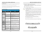
1.  Remove the disinfection system from the shipping carton. For shipping purposes, 

the UV lamp is packed in a separate tube. Set the lamp aside for use later. The 

disinfection system should be mounted in the horizontal position, with the inlet/

outlet ports facing up. If the system must be installed in the vertical position, make 

sure the inlet port is the one at the bottom of the system. Mount the unit in a clear 

space with at least 36” (91.5 cm) of space at the lamp end to facilitate lamp and 

or quartz sleeve removal. Fasten the disinfection system to a suitable mounting 

platform with reinforcements.

2.  It is recommended to install a suitable flow restrictor in order that the flow rate. 

The use of a by-pass with shut-off valves is recommended for emergency use  

of untreated water when your disinfection system is being serviced. Apply 

two turns of Teflon tape around the port threads to ensure a tight join before 

connecting unions. 

Note:  

When the UV unit has been by-passed for service, the complete water system must be sterilized once 

again with chlorine to destroy any contamination that may have passed during by-pass.

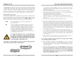
DO NOT SOLDER CONNECTIONS WHILE ATTACHED TO THE DISINFECTION SYSTEM AS 

THIS COULD DAMAGE THE O-RING SEALS.

3.  When all plumbing connections are made, slowly turn on the water supply and 

check for leaks. The most likely cause for leaks is from the O-ring seal. In case of a 

leak, shut water off, drain cell, remove the retainer nut, wipe the O-ring and threads 

clean and re-install.

4.  Once it is determined that there are no leaks, very carefully slide the UV lamp into 

the UV chamber making sure the lamp pins are accessible for connection with the 

lamp connector cable. Attach the lamp connector to the UV lamp, as outlined in 

“UV Lamp Replacement” on page 5. Plug the disinfection system into the ground 

fault interrupter, and check to see if the UV lamp is illuminated. NEVER LOOK 

DIRECTLY AT THE BURNING UV LAMP.


Allow the water to run for a few minutes to 

clear any air or dust that may be in the cell.

C. Lamp Failure System


(UVA-1C, UVA-2C, UVA-4C, UV-6, UVA-8C, UVA-12C, UVA-24B – UVA-200B)

The audible alarm and indicator lights on the systems continuously monitor a lamp 
operation. If the lamp does not start at any time, the indicator red light will glow and 
audible alarm will sound. This alarm indicated the UV lamp is no longer operating and 
must be corrected. Please refer to Troubleshooting Guide for corrective procedures.

Ultraviolet Monitoring System

The ultraviolet system features a complete warning system for continuous water 
protection by constantly sensing the UV light operation. The system features a single 
LED indicator light, which will operate two distinct colors, GREEN and RED. When the  
UV output level changes, the warning system will operate in the following manner:

GREEN -  

indicates that the UV lamp is satisfactory and the unit is in  


good working order. 

RED -  

indicates that the unit needs immediate attention, the audible 


alarm will automatically sound when the LED monitor light 


switches to red If the lamp has been in service for a year or more 


it should be replaced.  The quartz sleeve and/or sensor probe 


may require cleaning. The alarm will continue until the sensor 


detects adequate UV intensity. When a lamp is replaced it is 


recommended to clean the quartz sleeve and sensor probe prior  


to returning the system to service.

THIS ADVANCED WARNING SYSTEM HAS BEEN INSTALLED 

TO PROVIDE YOU WITH THE OPTIMUM PRECAUTIONS TO 

ENSURE HIGH EFFICIENCY IN THE PROTECTION AGAINST 

MICROBIOLOGICAL CONTAMINATION IN YOUR WATER.  

DO NOT DISREGARD THE WARNING LIGHTS.

THE BEST WAY TO CHECK UV OPERATION IS TO HAVE THE WATER TESTED FOR BACTERIA 
BY A RECOGNIZED TESTING AGENCY ON A REGULAR BASIS.
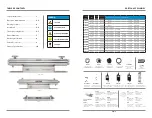
UVA-1C

UVA-2C

Summary of Contents for UVA-12C

Page 1: ... 302 83 9 000 39W 110V 220V LED INDICATOR w ALARM 6 2 OR 2 5 FLANGE STAINLESS 304 36 93 6 26 125 PSI 35o F 104o F 1 67o C 40o C 254 nm 30 mJ cm2 UVA 100B 100 378 54 9 000 39W 110V 220V LED INDICATOR w ALARM 8 2 OR 2 5 FLANGE STAINLESS 304 36 93 8 62 125 PSI 35o F 104o F 1 67o C 40o C 254 nm 30 mJ cm2 UVA 150B 150 567 81 9 000 87W 110V 220V LED INDICATOR w ALARM 6 3 FLANGE STAINLESS 304 36 93 8 62 ...

Page 2: ...AGILE LEGEND UVA 8C UVA 24B UV PLUG Plastic Plug for Nuts for Models UVA 6C UVA 200B UV 32SPRING Stainless Steel Spring for Model UVA 8C UV TIMER Counter Timer for Models UVA 24B UVA 200B UV 39SPRING Stainless Steel Spring for Models UVA 12C UVA 200B BEB 1024 Ballast for 10W 17W 110V 220V for Models UVA 1C UVA 4C BEB 2439 Ballast for 24W 39W 110V 220V for Models UVA 6C UVA 12C UV SEAL Seal for Sle...

Page 3: ... at an effective life of approximately 9000 hours To ensure continuous protection replace the UV lamp annually Polaris Scientific UltravioletTM warrants the ultraviolet disinfection system s hardware and electrical systems to be free from defects in material and workmanship for a period of five 5 years from the date of purchase by the original owner on a pro rated basis Polaris Scientific Ultravio...

Page 4: ...e UV lamp The connector is keyed and will only allow correct installation in one position Ensure the connector is fully seated onto the UV lamp 3 Once the lamp is fully seated on the connector slide the connector over the aluminum retaining nut Make sure the metal retaining ring on the connector is pulled away from the body of the connector in order that the connector may slide fully over the reta...

Page 5: ...e gland nuts hand tight is sufficient h Re tighten all connections turn on water and check for leaks i Re install the UV lamp and lamp connector as per prior instructions j Reconnect system to power source Note If the system is put on a temporary by pass or if it becomes contaminated after the disinfection system itwillbenecessarytoshockthesystemwithhouseholdbleachforafull20minutesbeforeresumingus...

Page 6: ...In case of a leak shut water off drain cell remove the retainer nut wipe the O ring and threads clean and re install 4 Once it is determined that there are no leaks very carefully slide the UV lamp into the UV chamber making sure the lamp pins are accessible for connection with the lamp connector cable Attach the lamp connector to the UV lamp as outlined in UV Lamp Replacement on page 5 Plug the d...

Page 7: ...In case of a leak shut water off drain cell remove the retainer nut wipe the O ring and threads clean and re install 4 Once it is determined that there are no leaks very carefully slide the UV lamp into the UV chamber making sure the lamp pins are accessible for connection with the lamp connector cable Attach the lamp connector to the UV lamp as outlined in UV Lamp Replacement on page 5 Plug the d...

Page 8: ...e gland nuts hand tight is sufficient h Re tighten all connections turn on water and check for leaks i Re install the UV lamp and lamp connector as per prior instructions j Reconnect system to power source Note If the system is put on a temporary by pass or if it becomes contaminated after the disinfection system itwillbenecessarytoshockthesystemwithhouseholdbleachforafull20minutesbeforeresumingus...

Page 9: ...e UV lamp The connector is keyed and will only allow correct installation in one position Ensure the connector is fully seated onto the UV lamp 3 Once the lamp is fully seated on the connector slide the connector over the aluminum retaining nut Make sure the metal retaining ring on the connector is pulled away from the body of the connector in order that the connector may slide fully over the reta...

Page 10: ... at an effective life of approximately 9000 hours To ensure continuous protection replace the UV lamp annually Polaris Scientific UltravioletTM warrants the ultraviolet disinfection system s hardware and electrical systems to be free from defects in material and workmanship for a period of five 5 years from the date of purchase by the original owner on a pro rated basis Polaris Scientific Ultravio...

Page 11: ...AGILE LEGEND UVA 8C UVA 24B UV PLUG Plastic Plug for Nuts for Models UVA 6C UVA 200B UV 32SPRING Stainless Steel Spring for Model UVA 8C UV TIMER Counter Timer for Models UVA 24B UVA 200B UV 39SPRING Stainless Steel Spring for Models UVA 12C UVA 200B BEB 1024 Ballast for 10W 17W 110V 220V for Models UVA 1C UVA 4C BEB 2439 Ballast for 24W 39W 110V 220V for Models UVA 6C UVA 12C UV SEAL Seal for Sle...

Page 12: ... 302 83 9 000 39W 110V 220V LED INDICATOR w ALARM 6 2 OR 2 5 FLANGE STAINLESS 304 36 93 6 26 125 PSI 35o F 104o F 1 67o C 40o C 254 nm 30 mJ cm2 UVA 100B 100 378 54 9 000 39W 110V 220V LED INDICATOR w ALARM 8 2 OR 2 5 FLANGE STAINLESS 304 36 93 8 62 125 PSI 35o F 104o F 1 67o C 40o C 254 nm 30 mJ cm2 UVA 150B 150 567 81 9 000 87W 110V 220V LED INDICATOR w ALARM 6 3 FLANGE STAINLESS 304 36 93 8 62 ...

Reviews: