background image

- 23 -

1200_GB-ANHANGA_SICHERHEIT

Supplement - A

EN

Recommendations for work safety 

Recommendations for work safety 

All points refering to  safety in this manual are 

indicated by this sign.

1.  Operating instructions

a.  The operating instructions are important for the correct 

operation of the machine. Make sure that the operating 

instructions are always on hand when operating the 

machine.

b.  Keep the operating instructions as long as the machine 

is in your hands.

c.  Pass the operating instructions on to the buyer when 

selling the machine.

d.  Make sure that all safety and warning symbols remain 

attached on the machine and keep them readable. The 

hazard warnings provide important information for a 

safe operation and, thus, your safety.

2.  Qualified personnel

a.  Only persons of legal age, mentally and physically able 

and having been trained or familiarized accordingly must 

operate this machine.

b.  Persons not yet trained or familiarized or under training 

must only operate this machine under the supervision 

of an experienced person.

c. Inspection, setting and repair work must only be 

performed by authorized persons.

3.  Repair work

a.  These instructions only refer to service, maintenance 

and repair operations the user is able to carry out 

without assistance. Any work beyond this scope has 

to be carried out at authorized workshops only.

b.  Repairs on the electrical and hydraulic system, preloaded 

springs, pressure accumulators, etc. require sufficient 

knowledge, correct tools and protective clothing and, 

thus, must only be performed at authorized workshops.

4.) Defined  use

a.  See "Technical Data". 
b.  The keeping of operating, service and maintenance 

requirements layed down by the manufacturer also 

come under the heading of "defined use".


5.) Spare parts

a.  The original components and accessories have been 

designed  especially for these machines and  appliances. 

b.  We want to make it quite clear that components and 

 accesories that have not been supplied by us have not 

been tested by us. 

c.  The installation and/or use of such products can, 

 therefore, negatively change or  influence the 

construction  characteristics of the appliance. We are not 

 liable for  damages  caused by the use of  components 

and  accessories that have not been  supplied by us. 

d.  Alterations and the use of auxiliary parts that are not 

permitted by the  manufacturer render all liability invalid. 

6.) Protection devices

a.  All protection devices must remain on the machine and 

be maintained in proper condition. Punctual replacement 

of worn and damaged covers is essential.

7.) Before starting work

a.  Before commencing work, the operator must be aware 

of all operating devices and  functions. The learning 

of these is too late after having  already commenced 

 operation!

b. The vehicle is to be  tested for traffic and  operating safety 

before each  operation. 

8.) Asbestos 

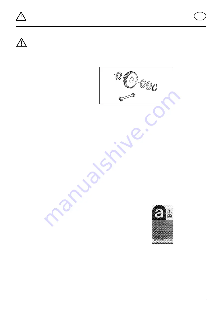
a. Certain sub-supplied components 

of the  vehicle may contain  asbestos 

due to  technical reasons. Observe 

the warning on spare parts. 

Summary of Contents for EUROTOP 421 A TOPTECH PLUS

Page 1: ...ranslation of the original Operating Manual Nr 99 2611 EN 80U 0 Rotary Swather EUROTOP 421 A TOPTECH PLUS Type SK 2611 Chassis Nr 00787 MaschNr 01787 EUROTOP 461 A TOPTECH PLUS Type SK 2991 Chassis Nr 00357 MaschNr 01357 ...

Page 2: ... highest quality standards to our products which are constantly monitored by our in house quality management and our management board Because the safety perfect function highest quality and absolute reliability of our machines in operation are the core competencies for which we stand There may be deviations between these instructions and the product as we are constantly developing our products The...

Page 3: ... in the hand over declaration online Machine checked according to delivery note All attached parts removed All safety equipment drive shaft and operating devices at hand Operation commissioning and maintenance of the machine or device discussed and explained to the customer on the basis of the operating instructions Check tyres for correct air pressure Check wheel nuts for tight fit Correct PTO sh...

Page 4: ...osition 10 Operation Preparations for operation 11 Important before starting work 11 p t o speed 11 Hydraulic servo valve ST 11 General guidelines for working with the implement 12 Setting the cam track 12 Hydraulic swath apron optional 13 Safety advice 14 General maintenance information 14 Cleaning of machine parts 14 maintenance Parking in the open 14 Winter storage 14 Cardans 14 Hydraulic unit ...

Page 5: ...onforms to the engineering guideline regulations and the other relevant EU guidelines EU Declaration of Conformity By signing the EU Declaration of Conformity the manufacturer declares that the machine being brought into service complies with all relevant safety and health requirements Do not enter rotor area while driving motor is running Never reach into the crushing danger area as long as parts...

Page 6: ...t and right lifting struts 4 must be the same length 2 Secure the plug in bolts with pins 3 Fix the hydraulic lower link 5 so that the implement cannot swivel out to the sides 4 Swivel up the supporting leg 10 and secure it with bolts 5 Set the tractor hydraulic unit at the right height H Pay attention to have a sufficient distance to the cardan shaft X especially if you drive over ground tops 6 C...

Page 7: ...A1 on uneven surfaces PTO shaft guarding Before initial use you must check and if necessary adjustthecardanshaftlength seealsochapter Setting of cardan shaft in Annex B Important Always couple the wide angle link to tractor not to machine Beware P t o must be switched off be fore carrying out any work in the rotor area Setting the threaded spindle Set distance X1 1 Couplethemachinetothetractorandb...

Page 8: ...wering A E TD 26 92 16 s h 0 ST The machine can be lowered both from the working position and from the transport position Park machine stabily Secureimplementfromrollingusingwheel chocks Support Stand for EUROTOP 421 A Swing support stand down 5a secure with locking pin B Support Stand for EUROTOP 461 A Swing support stand down 5a secure with locking pin B Pull off drive shaft and rest on support ...

Page 9: ...tions before travelling Important information can also be found in the supplement of this operating manual Hydraulic lower link Fix the hydraulic lower link U in such a way that the machine cannot swing out sideways Take care when turning on slopes Take care The tractor s travelling characteristics are influenced by the weight G of the rotor unit Thiscanleadtodangeroussituations especially on slop...

Page 10: ...Transport position Changing to Transport position 1 Use single action control valve ST 2 Lower machine to ground 3 Slide trap sheet 9 completely in and secure with T screw K 4 Swing all guard rails 10 up Thelockingpinscatchautomaticallyinthefinalposition 5 Detach all tine arms and put on position 1 Attention If not all tine arms are taken off the rotor hastobesecuredagainstturningbymeans of the fo...

Page 11: ...becomes dirty or turf becomes damaged if the setting is too low 010 04 17 A1 Important before starting work 1 Switch on p t o Only switch p t o on when all protective fittings covers protective cloths claddings etc are in good order and are affixed to implement in the protection position 2 Onlyswitchthemachineoninworkingposition and do not exceed the specified p t o speed max 540 rpm A transfer lo...

Page 12: ...ional Tine height is set by appropriately positioning the linch pin V Tines should lightly touch the ground Fodder becomes dirty or turf becomes damaged if the setting is too low 159 02 39 V Setting the cam track The cam track can be adjusted if grass is left lying outside the swath 1 Park the machine on an even surface and secure it against rolling off Use wheel chocks 2 Take the three plastic pl...

Page 13: ... optional Operation 1 Automatic lowering of the hydraulic swath apron Pull the cord to change the hydraulic valve 2 Raising the hydraulic swath apron Pull the cord to change the hydraulic valve and to relieve the swath apron cycle Operate control unit on tractor ...

Page 14: ...se observe the following for maintenance The instructions in these Operating Instructions apply If no particular instructions are available here then the informationintheinstructionssuppliedbytherespective cardan shaft manufacturer apply General maintenance information Please observe the infiormation below to maintain the implement in good condition even after a long period in operation Re tighten...

Page 15: ...his indicate one or several lubrication points Remove cover 90 Greaselubricationpointsaccordingtolubricationchart FETT PTO shaft guarding Lubricate PTO shafts every 8 operating hours Take out the sliding profiles and lubricate well FETT 1 1 1 20h 1J 20h 100 h 1 1 1 1 1 1 1 100 h 212 03 06 V 0 8 Liter 1J Lubrication chart ...

Page 16: ...d between the intake and output control see below Re tightenboltsM12x110with1xnutand2xNordlock washers see Fig tightening torque 140 Nm PositiontheNordlockwasherswiththeroughmilling inside on top of one another This means that both washers have the fine milling outside Note Pay attention to the position of the dowel pins see Detail B Fig 289 12 20 Securecoveronthenewtinearm insertbetweenthe covers...

Page 17: ...r unit Cam track Interval 50 h Implementation Apply the grease gun to the grease nipple 1 Turn the rotor to ensure that the grease is evenly distributed Apply 3 4 strokes during a full rotation Make 3 4 full rotations 1 TOP 421A TOP 461A Be advised Check distance A of shaft W at least 1x annually Spring tines Check the attachment bolts S of the spring tines after the first 10 hours in operation an...

Page 18: ... once a year 100 ha every 100 hectares BB if necessary FETT GREASE Oil Number of grease nipples Number of grease nipples III IV see supplement Lubrificants l Litre Variation See manufacturer s instructions Rotations per minute 15 mm 10 mm 100 12 06 Always screw in measuring stick up to stop ...

Page 19: ...ingle action hydraulic connection pressure min 120 bar pressure max 180 bar 7 pole electric connection for lighting 12 Volt All data is subject to change 4100 mm EUROTOP 421 A 2100 mm EUROTOP 421 A 4300 mm EUROTOP 461 A 2430 mm EUROTOP 461 A EUROTOP 461 A Type SK 2991 Number of rotors 1 Number of tine arms per rotor 12 Number of double tines per tine arm 4 Working width raking width 4 6 m Transpor...

Page 20: ...The keeping of operating service and maintenance requirements layed down by the manufacturer also come under the heading of defined use Important Please enter the number onto the front page of the operating manual immediately after taking delivery of the vehicle implement Position of Vehicle Identification Plate The chassis number is engraved on the name plate illustrated on the left Warranty clai...

Page 21: ...GB Anhang Titelblatt _BA Allgemein EN Supplement ...

Page 22: ...cheap buy can sometimes be very expensive Be sure you purchase the Original with the cloverleaf sym bol Quality and precise fitting Operating safety Reliable operation Longer lasting Economy Guaranteed availability through your Pöttinger Sales Service Things will run better with genuine Pöttinger parts The original cannot be copied ...

Page 23: ...dhydraulicsystem preloaded springs pressure accumulators etc require sufficient knowledge correct tools and protective clothing and thus must only be performed at authorized workshops 4 Defined use a See Technical Data b The keeping of operating service and maintenance requirements layed down by the manufacturer also come under the heading of defined use 5 Spare parts a Theoriginalcomponentsandacc...

Page 24: ...nto account the working range and swing mass of the implement 11 General a Beforeattachingimplementtothree pointlinkage move systemleverintoapositionwherebyunintentionalraising or lowering is ruled out b Danger of injury exists when coupling implement to tractor c Danger of injury through crushing and cutting exists in the three point linkage area d Do not stand between tractor and implement when ...

Page 25: ...se clean and lubricate driveshaft For winter working grease the tube guards to avoid them freezing together 8 Adapting cardan shaft Thecorrectlengthisdeterminedbycomparingbothcardan shaft halves Procedure for cutting to length To adjust length hold cardan shaft halves next to each other in the shortest operating position L2 and mark Caution Note the maximum operating length L1 Try for the greatest...

Page 26: ...oadprotectiondevicedesigned to protect your vehicle against damage Sensibledrivingavoidsfrequentengagingoftheclutchand preventsunnecessaryweartotheclutchandtheimplement Greasing interval 500 hrs Special lubricant Important for driveshafts with friction clutch Torque is limited with overloading and brief torque peaks and evenly transferred during slipping Prior to initial operation and after long p...

Page 27: ...east once a year Take out oil drain plug let run out and duly dispose waste oil Before garaging winter season an oil change and greasing of all lubricating points has to be done Unprotected blanc metal parts outside joints etc have to be protected against corrosion with a group Iv product as indicated on the reverse of this page Corrosion protection Fluid 466 Lubricants Edition 2013 Lubricant indi...

Page 28: ...BEÖL B 85W 90 GETRIEBEÖL C 85W 90 LORENA 46 LITORA 27 RHENOX 34 GETRIEBEÖL B 85W 90 GETRIEBEÖL C 85W 140 ELF OLNA 32 46 68 HYDRELF 46 68 PERFORMANCE 2 B SAE 30 8000 TOURS 20W 30 TRACTORELF ST 15W 30 TRANSELF TYP B 90 85W 140 TRANSELF EP 90 85W 140 EPEXA 2 ROLEXA 2 MULTI 2 GA O EP POLY G O MULTIMOTIVE 1 TRANSELF TYP B 90 85W 140 TRANSELF TYP BLS 80 W 90 ESSO NUTO H 32 46 68 NUTO HP 32 46 68 PLUS MO...

Page 29: ... 32 46 68 SUPER TRAC FE 10W 30 ULTRAMAX HVLP 32 ULTRAPLANT 40 SUPER HPO 30 STOU 15W 30 SUPER TRAC FE 10W 30 ALL FLEET PLUS 15W 40 HP GEAR OIL 90 oder 85W 140 TRANS GEAR OIL 80W 90 MULTILUBE EP 2 VAL PLEX EP 2 PLANTOGEL 2 N RENOLIT LZR 000 DEGRALUB ZSA 000 DURAPLEX EP 1 HP GEAR OIL 90 oder 85W 140 VEEDOL ANDARIN 32 46 68 HD PLUS SAE 30 M U LT I G R A D E S A E 8 0 9 0 MULTIGEAR B 90 MULTIGEAR C SAE...

Page 30: ...erence to the other following EU directives and or relevant provisions Source of applied harmonised norms EN ISO 12100 EN ISO 4254 1 EN ISO 4254 10 Source of applied miscellaneous technical norms and or specifications Person responsible for documentation Josef Mairhuber Industriegelände 1 A 4710 Grieskirchen EC Conformity Declaration Original Conformity Declaration Markus Baldinger CTO R D Grieski...

Page 31: ...and weights are given as anindicationonly Responsibilityforerrorsoromissions not accepted Reproductionortranslationofthispublication inwhole orpart isnotpermittedwithoutthewrittenconsentofthe PÖTTINGER Landtechnik GmbH A 4710 Grieskirchen All rights under the provision of the copyright Act are reserved PÖTTINGER Landtechnik GmbH werkt permanent aan de verbetering van hun producten in het kader van...

Page 32: ...TTINGER Landtechnik GmbH Industriegelände 1 A 4710 Grieskirchen Telefon 43 7248 600 0 Telefax 43 7248 600 2513 e Mail info poettinger at Internet http www poettinger at PÖTTINGER Deutschland GmbH Verkaufs und Servicecenter Recke Steinbecker Strasse 15 D 49509 Recke Telefon 49 5453 9114 0 Telefax 49 5453 9114 14 e Mail recke poettinger at Pöttinger France S A R L 129 b la Chapelle F 68650 Le Bonhom...

Reviews: