


Cardox Techical Manual
Page
13
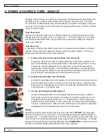
male end of the clamp.
8.06 The clamp needs to be securely tightened in place on the tube. Hitting the clamp
with the wrench will verify that the clamp is in place securely.
8.07 When the base port is located close to a tower edge or corner wall only a 2-way
discharge head should be used. Mark the direction of discharge by aligning the
handle or the bolt on the clamp with the 2-way discharge outlet opening. When the
tube is locked in the base port, observe the direction the blast will go. Adjust the
positioning of the clamp so that the discharge will be in the vertical direction.
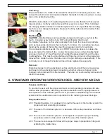
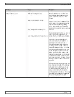
8.08 Next the firing wires should be placed in the activation auto fill head. The electrical
application is not polarity sensitive and as such no particular orientation of the firing
cable wires is needed. The opposite end of the firing cables should remain shunted
(twisted) together until the tube is placed in the base port, this prevents static elec-
tricity from the tube prematurely.
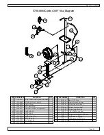
8.09 Place the tube with clamp into the base port and twist it into a locked position. Move
to the opposite end of the firing cable, which should be around a corner or out of
the line of the tube direction by 25’ – 30’. Hook up the MHSA approved blaster.
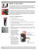
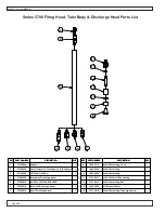
8.10 Observe that the area around the blast is secured. Hold the left button down on the
blaster until the red light comes on. Continue to hold the left button with the light on
and depress the right button to activate the safety heater inside the tube.
8.11 The blast should occur immediately. NOTE: the goal is to have the tube inside of
the tower heat for less than 5 minutes. Once the blast has occurred remove the
blaster and re-shunt that end of the firing cables.
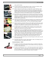
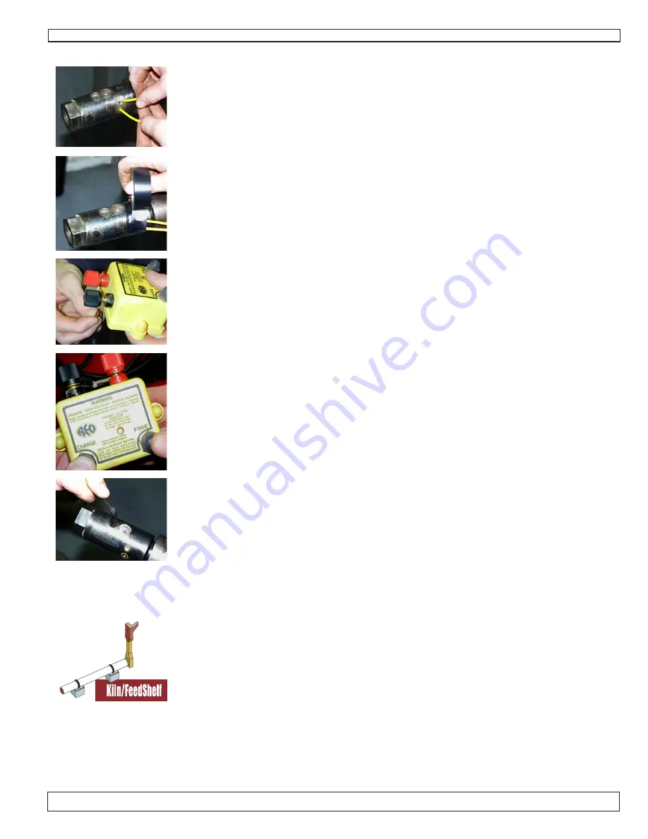
8.12 If a blast does not occur, immediately approach the tube. Observe the location of
the relief hole in the fill head. Make certain that the relieved gas will not strike you in
the face. Open the safety bleeder valve using a 1/4” hex wrench. Let the gas bleed
off before removing the tube. Relieving this pressure will cause the inside of the
tube to go back to equal pressure with the outside. The heater in the tube cannot
function unless it has a constant pressure around it that is greater than 275 PSI.
After relieving the gas from inside of the tube will be less than the 275 PSI.
8.13 Remove the tube. Remember that by now the discharge end of the tube is very hot;
so handle accordingly.
8.14 This failed to blast tube should be marked properly or take it to the filling room and
carefully dismantle it according to section #6.03
Cardox Activation – KILN
8.15 To properly use Cardox to break up kiln build up rings – the base ports need to be
installed in the kiln wall while shut down in the locations that the ring is expected to
be based on past experiences.
8.16 The kiln can be drilled with it “hot” or “cold”. Proper precautions need to be taken to
work the kiln hot. The work can be done off a man lift machine or off a catwalk. The
kiln can be stopped for 15 – 30 minutes at a time and the hole drilled in the build
up. The kiln can then be rotated for the desired number of rotations.
Summary of Contents for Cardox CO2
Page 1: ...A B C D 8 7 6 TECHNICAL MANUAL 110 Mohr Drive Mankato MN 56001 1 800 458 9446 www pneumat com ...
Page 22: ...Cardox Techical Manual Page 22 5780 0005 Cardox Fill Stand Assembly Parts List ...
Page 25: ...Cardox Techical Manual Page 25 5730 0003 Auto Fill Activating Head w Eyebolt Parts List ...
Page 27: ...Cardox Techical Manual Page 27 Series 3700 Firing Head Tube Body Discharge Head Parts List ...
Page 28: ...Cardox Techical Manual Page 28 Series 5700 Firing Head Tube Body Discharge Head Parts List ...


