Plymovent SBT-Pneumatic SBTP-6-100-100 Product User Manual Download Page 2

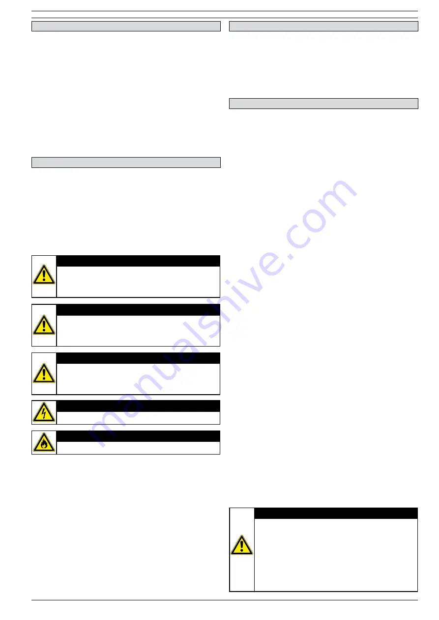
ATTENTION

A remark with additional information for the user. 
A remark brings possible problems to the user’s 
attention.

CAUTION!

Procedures, if not carried out with the necessary
caution, could damage the product, the workshop or
the environment.

WARNING!

Procedures which, if not carried out with the 
necessary caution, may damage the product or cause 
serious personal injury.

WARNING!

Denotes risk of electric shock.

WARNING!

Important warning to prevent fire.

PUM_SBT_091102_EN

2/38

PREFACE

Using this manual

This manual is intended to be used as a work of reference for
professional, well trained and authorized persons / user’s to 
be able to safely install, use, maintain and repair the product 
mentioned on the cover of this document.

Pictograms and symbols

The following pictograms and symbols are used in this manual:

Service and technical support

For information about specific adjustments, maintenance or 
repair jobs which are not dealt with in this manual, please 
contact the supplier of the product. He / she will always be 
willing to help you.

Make sure you have the following specifications at hand:
- The SBT Pneumatic product user manual

1. IMPORTANT SAFETY INSTRUCTIONS

Please read these instructions before installing the Sliding 
Balancer Track (hereafter called SBT) system.  This will help 
you obtain the full benefit from the exhaust removal system 
you have selected.

A. Read the Product user manual and Safety Instructions 
  carefully. Failure to follow these instructions could   


  cause a malfunction in the system or unsatisfactory 
  performance. 

B. Follow a regular service and maintenance schedule for
  efficient operation.

1.1 Identification of the product

The SBT system is made up out of various different parts 
which together form the SBT-Exhaust Removal System.  All 
these individual parts can be traced back to this product 
user manual. 

2.        INTRODUCTION

3.        PRODUCT DESCRIPTION

The SBT system consists of a number of parts of which the 
Plymovent yellow and black extraction hose assembly is most 
visible to the user. 

The extraction hose has a Safety Disconnect Coupling built 
in, this to protect the system against misuse. The hose is 
positioned in the Saddle which connects to the balancer. The 
balancer is connected to the aluminium track via a special 
trolley. This enables the balancer to move inside the aluminium 
profile which is positioned above and to the tailpipe side of the 
vehicle. 

The aluminium profile is designed to a three (3) section  
principle of which two (2) sections have open areas, one on 
the underside and one on the overside. The overside open area 
is used for positioning the support legs, duct and exhaust hose 
connector and the release valve.  The underside open area is 
used for positioning the end stops and for the sliding the  
trolley. 

Method of use: 

An automatic, pneumatic controlled exhaust gas extraction 

system, specially designed for fire and rescue vehicles with low 

level, side exhaust pipes. The system is used to remove the 

poisonous petrol and diesel gas fumes direct at the emission 

source, the exhaust pipe.  


When the vehicles are on their way out of the station, the 

extraction hose, connected to the exhaust by a special device 

called a Grabber®, moves along with the vehicle.  


Poisonous diesel gases pass from the Grabber®, up the  

extraction hose and into the ducting and extraction fan before 

escaping to the atmosphere.  
As the vehicles drive out through the doors, the trolley moves 

over a release valve on the track, which releases the air  

pressure in the Grabber® allowing it to disconnect the ex-

haust pipe. 

 
On the return of the vehicle to the station, The SBT  
Pneumatic Grabber

®  

is easily re-connected to the exhaust 

pipe.  At the same time the fan automatically starts up and the 

vehicle continues to its standard park position.

WARNING!

The use of exhaust removal hose is allowed for: 
- Moving of diesel-vehicles in- or out halls / stations.
- Short time maintenance work of diesel-vehicles,  
  but only if the engine is running on the minimum  
  rpm.
- The vehicle must leave and enter the station with  
  a modified speed in order to avoid damage to the    
  system and possible injury to people.  

Summary of Contents for SBT-Pneumatic SBTP-6-100-100

Page 1: ...USA Plymovent Corp 115 Melrich Road Cranbury New Jersey 08512 USA Tel 1 609 395 3500 Fax 1 609 655 0919 info plymovent com 1 Important safety instruction 2 2 Introduction 2 3 Product description 2 4...

Page 2: ...and black extraction hose assembly is most visible to the user The extraction hose has a Safety Disconnect Coupling built in this to protect the system against misuse The hose is positioned in the Sad...

Page 3: ...o be played with Intended use 1 The product has been designed as an exhaust removal system using the Grabber coupling system Using the product for other purposes is considered contrary to its intended...

Page 4: ...always has full responsibility for the correct execution of the safety guidelines and instructions These are all the safety guidelines and instructions which apply to the use of the system Service ma...

Page 5: ...C 338F and an air pressure of max 8 0 bar USA hose is 400 F continuous and 500 F intermittent Only activate the Grabber when placed on the tailpipe Do not bend over in the direction of the tailpipe w...

Page 6: ...g The aluminium support leg is used for both vertical and horizontal mounting The standard length is 5790 mm 19 feet and it has to be cut to proper lengths during instal lation The dimension of the su...

Page 7: ...1 and 2 Then adjust the bracket to an exact position and fix it by drilling a third hole 3 using the most centrered hole from the top row Adjustable mounting kit horizontal The bracket that shall be u...

Page 8: ...25 mm 5 Length 6m 19 6 feet or 10m 33 feet Grabber 120mm 4 7 or 160mm 6 3 The different hose packages which contain the following parts Transition parts and regulator Exhaust removal hose 150 C 302 F...

Page 9: ...Common material Common materials that are always included are gathered under product no SBT KIT Pneumatic Material included in the kit are Release valve End stop Security tape marking Trolley Balance...

Page 10: ...the exhaust pipe have 2 Measure the height and width of the gate 2 Check what type of gate Slidegate Overhead gate Other type Check at what height the track can be installed 3 Measure the distance be...

Page 11: ...t height the SBT track can be installed 3 Measure the distance between the gate and the exhaust pipe 3 this is the required minimal length of the SBT track Check before installation that this is the m...

Page 12: ...ctional door 3 with a clear height from the track to the door of 100mm 4 to 150 mm 7 The SBT track is placed 160mm 6 3 to 508mm 20 5 from the truck side of the vehicle The recommended distance from th...

Page 13: ...please use a wall mounting bracket to attach the front solidly 2 The rear support 2 is placed approximately 1000 mm 40 from the rear of the SBT profile 3 Depending on the lenght of the SBT track addi...

Page 14: ...e SBT track additional supports have to be mounted The distance from the first installation bracket to the front and respectively the end of the rail should be minimal 1 5m 5 feet The distance between...

Page 15: ...e side of the vehicle c The hose connection connector 2 is placed at the point calculated as followed Distance Exit door to exhaust pipe 3 divided by half 6 plus 500mm 20 inch 7 This is the position o...

Page 16: ...ction 2 is mounted on the SBT track on the opposite side of the vehicle c At a drive through station the hose connection 2 shall be positioned on the SBT track 1 at the half distance between entrance...

Page 17: ...e bracket see Hose connection mounting procedure in this product user manual is inserted in the profile d Drill two holes in the support leg 2 one for the upper and one for the lower bracket 6 Mount t...

Page 18: ...udinal brace 3 is mounted in a separate bracket Use M10x20 and locking nut 4 check that the support is vertical before the bolts are fastened WARNING PRODUCT MAY CONTAIN SHARP EDGES Use care when serv...

Page 19: ...bolts 4 to the SBT Profile 1 Also insert the mounting clamp for the hose bracket see hose connection mounting procedure Next to this insert the disconnect valve bracket 6 between the first and second...

Page 20: ...onnection are inserted in the profile 1 together with the mounting clamps for the support legs see support legs mounting procedure in this product user manual b The hose connection 2 is tightened in p...

Page 21: ...p b Be sure you have the SBT track 1 in equal length covered by the splicing sleeve 2 c Check that you have the splicing sleeves in equal position d Drill 6mm holes through the SBT track using the pre...

Page 22: ...rs 3 are applied on both sides of the SBT track 1 on the hazard tape 2 600mm 24 from exit end 8 INSTALLATION HOSE ALIGNMENT PROCEDURE 1 SBT hose 2 Grabber nozzle 3 MFD valve 4 Hose saddle The exhaust...

Page 23: ...and the safety chain facing towards the back of the parking area Please see balancer instructions for the correct settings of the balancer c The Balancer locking cable is connected between the hose sa...

Page 24: ...nnection 2 location also affects the loop height also see Trimming procedure c Hose loop height 3 should not be less than 2 0m 6 5ft not to be in the way of fire personnel d The hose saddle 5 should b...

Page 25: ...sor is tight and both connection points are upwards Connect the electric wires with the supplied connection tags Or connect the PC 500 pressure switches to the wireless transmitters Tip when using mor...

Page 26: ...mounting clamp 3 on the underside of the track and then the locking nuts on the carriagebolts 4 are tightened Make sure the locking nuts are tightly fastened c The endstop without shock absorber 5 is...

Page 27: ...file for a LEFT side exhaust the release valve 1 has to be changed as follows Unscrew the bolts and nuts 2 turn the valve with the knee 3 pointing to the gate reassemble the valve on the bracket 4 Che...

Page 28: ...the Grabber reaches the exit door b At correct length of the exhaust hose 0 5 1m of wire should be out of the balancer 3 when the Grabber is at disconnect point c The exhaust hose is cut to length wi...

Page 29: ...the SBT profile with the toggle joint 5 pointing towards the gate approximately 1800 mm from end of track The valve is fitted with the mounting clamp 4 bolt M6x20mm and washer 3 Check that the release...

Page 30: ...alancer counter clockwise until the rubber stop hits the balancer b Add two more quarter clicks to ensure full retraction of the balancer cable It s possible the balancer tension needs to be fine tune...

Page 31: ...two plastic parts together with the same 6 screws Hereby attaching the lower half of the SDCH to the upper half including the lower aluminium flange Insert the lower flange in the hose and tighten the...

Page 32: ...ugh the rubber inlet in the hose holder down through the exhaust hose to the side of the MFD valve 7 Use the colours of the air hoses for orientation From the MFD valve 7 an 8mm air hose connects down...

Page 33: ...ressed air hoses suspension halter MFD valve and Grabber The safety disconnect coupling should be disassembled and cleaned The hose assembly should be aligned prior to mounting see Alignement mounting...

Page 34: ...nd end stops 7 Check that the trolley trip plate activates the release valve correctly The release valve must be activated to 1mm from bottom position 8 Check the balancer see separate manual 9 Discon...

Page 35: ...is too far for ward The release valve or and the end stop should be moved further back onto the rail The Grabber opens when the vehic les drives into the station The release valve releases air when th...

Page 36: ...25 21 20 26 24 23 22 See separate Balancer manual 3 2 4 10 8 1 7 6 5 9 11 PUM_SBT_091102_EN 36 38 14 SPARE PARTS...

Page 37: ...39 29 30 31 32 33 34 35 37 36 38 35 PUM_SBT_091102_EN 37 38 14 SPARE PARTS...

Page 38: ...16 1 1 1 1 1 Hose Saddle 100 512 624 1 1 Hose Saddle 125 6 985 887 X Compressed air hose White 6mm 7 985 895 X Compressed air hose Yellow 6mm 8 985 960 X Compressed air hose 8mm 9 961 458 1 1 1 1 1 Ho...

Page 39: ...absorber 27 90100 1011 1 Balancer 28 90100 007 1 Spring 29 90100 010 1 Wire Complete 30 8150 1011 1 Adjustable mounting kit vertical 31 8260 1011 1 Adjustable mounting kit horizontal 32 8130 1011 1 Si...

Reviews: