


M
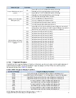
14 PCIe Connectors
PEX 8619
(U100)
8
Dipswitches
SW13-14
Xilinx
Spartan 3 FPGA
XC3S200-4FTG256C
(U115)
connectes to GPIOs,
Lane and chip status,
and spare Pins of
PEX8618
Mictor
Connectors
(JP9 & 11)
Communicates with the
thermal sensor and
displays the junction
temperature of PEX
8618
36 7-seg.
displays
Temperature in
4 digits
MAX
6658
2
Users’ defined
Dipswitches
RESET and PERST
circuits
14
From PCIe cable
connector J5 or on board
momentary switch S1
2
Decodes lane status
and converts to link
speed and status
displays
5Gbps
2.5Gbps
Thermal
Diode
Controls the 7-segment
displays of Port# and link
width of PCIe slots and cable
connectors of PEX 8618
Figure 13. FPGA Interface on RDK
3.10
LED and 7-Segment Displays
The RDK provides 31 LEDs and forty 7-segment displays for power indicators, Hot-Plug output indicators, link
speed/status, port numbers and link width of each port.
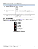
3.10.1
LED Indicators
All LED indicators and their associated functions are described in the
below.
Table 2. RDK LED Indicator descriptions
Indicator Type
Locations
LED Functions
Power LEDs/green color
D1
On: 12V_A is applied to the RDK from the ATX power supply
D2
On: 5V_A is applied to the RDK from the ATX power supply
D3
On: 3.3VCC is applied to the RDK from the ATX power supply
D9
On: 3.3VCC1 from dc/dc converter U4
D4
On: 2.5VCC_A is applied to PEX 8619
D5
On: 2.5VCC is applied to PEX 8619
D6
Power LED for 1.0VCC_A (did not work)
D7
Power LED for 1.0VCC (did not work)
PEX 8619BA Base Board RDK Hardware Reference Manual – Version 1.0
Copyright © 2008 by PLX Technology, Inc. All rights reserved
13


