


Building a Simple Voltage Source Inverter
A
A model comprised of Discrete IGBT components will show significant non-ideal harmonics
on the current waveforms at lower duty cycles. A 10 kHz PWM signal has a
100
µ
s
period,
so with a
2
.
0
µ
s
discretization step size it is only possible to sense 50 different duty cy-
cles. When a PWM Capture component is used the
7
.
5 ns
sampling resolution of the FPGA
results in the ability to sense 13,333 different duty cycles for the same 10 kHz PWM wave-
form.
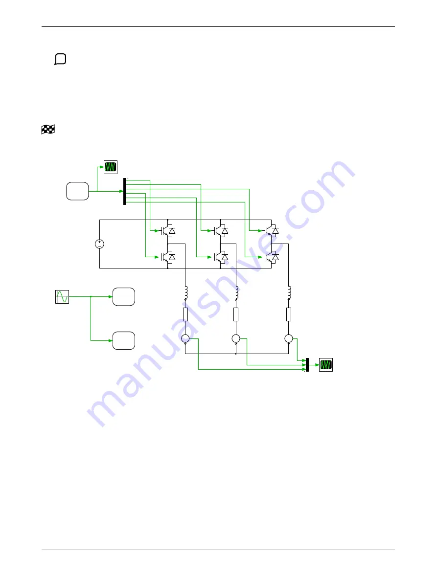
After completing these tasks, your model should be the same as the reference model
vsi_loopback_optional.plecs
.
Sine Wave
Frequency: 50
Phase: [0 -1 1]/3
Units: Hertz, p.u.
PWM Out1
channel: 0 2
polar: 1
PWM
Out
PWM Out2
channel: 3 5
polar: 0
PWM
Out
L1
L: 0.001
R1
R: 1
A
Am1
L2
L: 0.001
R2
R: 1
A
Am2
L3
L: 0.001
R3
R: 1
A
Am3
V_dc
V: 800
Current
PWM
Digital In1
channel: 0 5
Digital
In
Figure 2: A simple VSI model with conventional switches
4 Conclusion
Conventional switch models have limitations in real-time applications. The switch state can only be
updated once per simulation time step, requiring a relatively small discretization step size relative to
the PWM period. This leads to high processor utilization even for relatively simple models and poor
performance at low duty cycles.
The next several tutorial exercises will demonstrate how to overcome these modeling challenges by
using sub-cycle averaging and specialized hybrid power modules.
4