


Modular Multilevel Converter
and therefore fidelity of the real-time simulation is improved.
2.2 Controls
The demo model is operated in open-loop. The PWM generation is executed in the same box and
routed to the digital output be means of the PWM Out block. Those PWM signals are then feed back
to the digital inputs by using a physical loop-back cable. The PWM signals are then brought into the
real-time simulation with the PWM Capture block.
3 Simulation
This model can run both in offline mode on a computer or in real-time mode on the PLECS RT Box.
Please follow the instructions below to run in real-time mode on an RT Box:
• Connect the Digital In interface to the Digital Out interface of the RT Box, i.e. by using a 37 pin
Sub-D cable.
• From the
System
tab of the
Coder options...
window, select the “Plant” and go to the
Scheduling
tab. Chose either
single-tasking
or
multi-tasking
as the tasking mode and accept your choice.
Please note that multi-tasking mode is only available for RT Box 2 and RT Box 3.
• Return to the
System
tab, select the “Plant” and
Build
it onto the RT Box.
• Once the model is uploaded, from the
External Mode
tab,
Connect
to the RT Box and
Activate
autotriggering
.
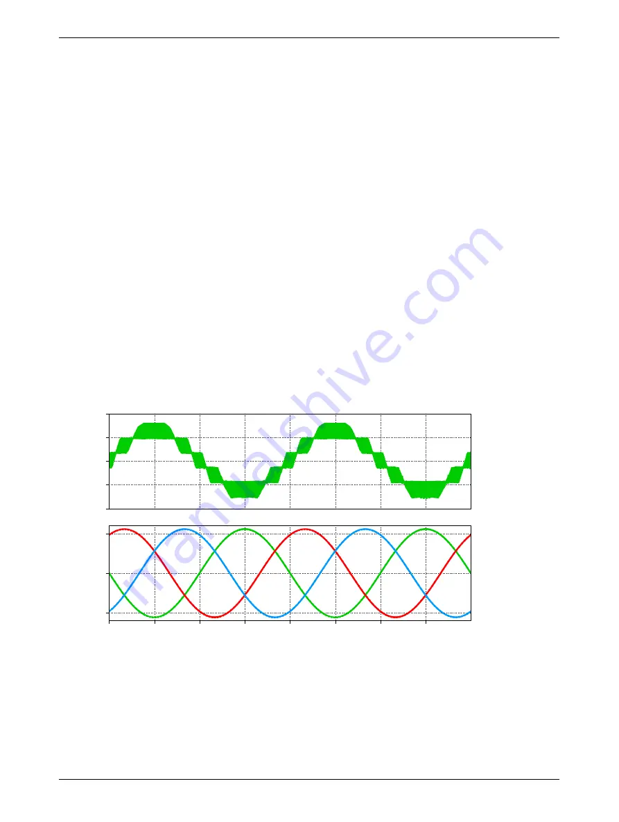
During the real-time operation under
External Mode
the measurements can be observed using the
PLECS Scope “Measurements”. The arm voltage and AC grid currents are shown in Fig. 5.
Arm Voltage
Grid current
vo
lt
ag
e
(V
)
-400
-200
0
200
400
× 1e-2
0.0
0.5
1.0
1.5
2.0
2.5
3.0
3.5
cu
rr
en
t
(A
)
-1000
0
1000
Figure 5: Real-time measurements obtained on the RT Box in multi-tasking mode
4 Conclusion
This RT Box demo model demonstrates a grid-connected MMC inverter under open-loop control. The
demo model can run both in single-tasking mode on one CPU core of the RT Box 1, 2 or 3, or in multi-
tasking mode on three CPU cores of the RT Box 2 or 3. Multi-tasking has the benefit that the average
execution time can be reduced considerably.
4


