


Modular Multilevel Converter
2.1 Power Circuit
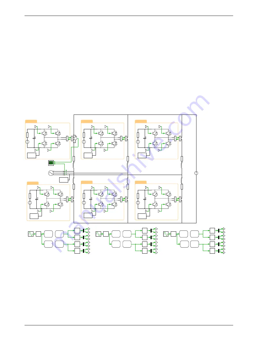
Fig. 2 shows the circuit model of the “Plant”, which comprises an MMC connecting the AC system and
the DC system. The MMC has a configurable number of submodules per arm with a default value of
5. Every submodule is composed of one full-bridge and a DC-link capacitor and each single-phase pair
of converter arms, together with their arm inductors, is then connected to the AC grid. The converter
arms are implemented with the Full Bridges (Series Connected) power module library component.
This component has two configurations: a Switched implementation where ideal switches represent
the semiconductors, and an sub-cycle averaged configuration that uses controlled voltage and current
sources. This model is configured to use the Sub-cycle averaged implementation of the power module
components which is suitable for offline and real-time simulation.
The implementation of both the power module and the PWM generation is such that the number of
cells can be configured with a variable
num_sm
in the Model initialization commands without having to
extend the model with additional wiring or components. This concept is called implicit vectorization of
the model structure and is further explained in the tutorial “Implicit Model Vectorization” available in
the tutorials section of the Plexim website.
Swa
PWM
Capture
PWMa
PWM
Out
ma
Qa+1
Qa+4
Qa+2
Qa+3
U(I)
Qa-2
Qa-3
Qa-1
Qa-4
Swb
PWM
Capture
PWMb
PWM
Out
mb
Qb+1
Qb+4
Qb+2
Qb+3
Qb-2
Qb-3
Qb-1
Qb-4
Swc
PWM
Capture
PWMc
PWM
Out
mc
Qc+1
Qc+4
Qc+2
Qc+3
Qc-2
Qc-3
Qc-1
Qc-4
U(I)
U(I)
U(I)
U(I)
U(I)
U(I)
U(I)
U(I)
U(I)
U(I)
U(I)
U(I)
U(I)
U(I)
PWMa1
PWM
Out
Swa1
PWM
Capture
PWMb1
PWM
Out
Swb1
PWM
Capture
PWMb2
PWM
Out
Swc1
PWM
Capture
Qa+3
Qa+4
Qa+1
Qa+2
Qa-3
Qa-4
Qa-1
Qa-2
V_3ph
Qb+3
Qb+4
Qb+1
Qb+2
Qb-3
Qb-4
Qb-1
Qb-2
Qc+3
Qc+4
Qc+1
Qc+2
Qc-3
Qc-4
Qc-1
Qc-2
V_dc
Model
Settings
Model
Settings
Model
Settings
Model
Settings
Model
Settings
Model
Settings
Model
Settings
V
Upper Side
Upper Side
Upper Side
Lower Side
Lower Side
Lower Side
Measurements
Figure 2: Schematic of the grid-connected MMC inverter
Tasking modes
In order to distribute the physical model on different CPU cores of the RT Box 2/3, the model has to be
split with the Task frame component from the PLECS library. The tasking mode can be configured in
the Coder Options in the
Scheduling
tab of the
Coder Options
window, as shown in Fig. 3.
Single-tasking
If the
Tasking mode
is configured as
single-tasking
, all task frame components
are ignored and the physical system is executed in a single base task. This configuration is needed for
real-time simulation of the demo model on the RT Box 1.
2


