SECTION C: Fitting the Liner
Fitting the Linerlock
• Linerlock is the white plastic extrusion that the pool liner hangs from.
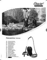
• Although the linerlock can be cut straight at a 90 degree angle a neater finish and better fixed liner will be achieved by cutting
at 22½ degrees. A mitre block will help with this.
• Take a length of linerlock and trim one end to approximatley 22½ degrees
[see figures 19 & 20]
.
• Clamp or hold this length of linerlock along the inside of one pool wall and mark the length. The correct length is to have the
linerlock for each wall meeting in the corner with only a minimal gap. Cut the other end to 22½ degrees.
• Lay the trimmed linerlock along the top of the pool wall and use a 3mm drill bit to make pilot holes starting 25mm in from each
end and at approximately 200mm - 250mm centres.
• Use the 3.5mm x 40mm screws to fix the linerlock to the inside of the wall
[see figure 20]
.
• The linerlock must be exactly flush with the top of the wall.
• Repeat this procedure for each wall ensuring that where the linerlock meets in the corners it is at the same level.
• It may be necessary to make some sections from two pieces as the Iinerlock is supplied in standard lengths, which do not divide
exactly into the correct sizes for all pools.
• Ensure that no linerlock screws are left protruding and have no sharp edges that could damage the liner.
Levelling the Floor
• If you have assembled your pool on a subsoil base rather than a concrete pad it is likely that the area inside the pool will have
become disturbed while you worked. If you used a concrete base this section is not required.
• Although the floor felt and liner could be fitted on uneven subsoil it is not recommended and a better finish with longer liner life
will be achieved by levelling the floor as follows.
• Draw a pencil line all around the inside on the pool wall 20mm up from the bottom.
• Remove any loose dirt from inside the pool.
• Use a dry mix of 5 parts sharp sand to 1 part cement and spread evenly over the floor.
• Use a straight edge and plastering float to achieve a flat, level finish.
• Do not let the sand and cement level go any higher than 20mm above the base of your pool where you made your pencil line.
• Moisture in the air and soil base will cure the sand and cement mix.
• Let the floor harden before proceeding.
Laying the Floor Felt Underlay
• Ensure the pool floor is clean and that no objects can fall into the pool. Any objects or dirt that remain in the pool when the liner
is fitted can either damage the liner or be unsightly for years to come.
• While climbing in and out of the pool make sure no dirt or debris is brought in. It is advisable to lay the floor felt underlay with
bare feet or just wearing socks.
• Locate the roll of underlay felt and underlay tape. Never use any other type of tape where it will come into contact with the liner.
• Lay out the felt to completely cover the pool floor, it will be necessary to trim the felt with scissors and join strips together using
the supplied underlay tape.
• Ensure that the felt is not overlapped at any point or creased as the double thickness will show through the liner.
• Where strips are laid side by side ensure the joint is butted up closely with no gap. Join sections of felt with the underlay tape.
• Avoid joining together edges that you have cut on site, most likely a neater finish will be achieved by joining machine cut edges.
Figure 19
Figure 20
8
11
Cutting in the Pool Flow Fittings
• Cutting the liner and fitting the flow fittings should be done with care and not rushed, it is wise to have a person outside the pool
so they can pass you tools and equipment.
• Do not cut the liner until you are completely happy with the liner position.
• Locate the screws, faceplates, gaskets and all other parts of the inlet, skimmer and optional under water light. Manufacturers
vary their designs so read through the instructions that came with each item.
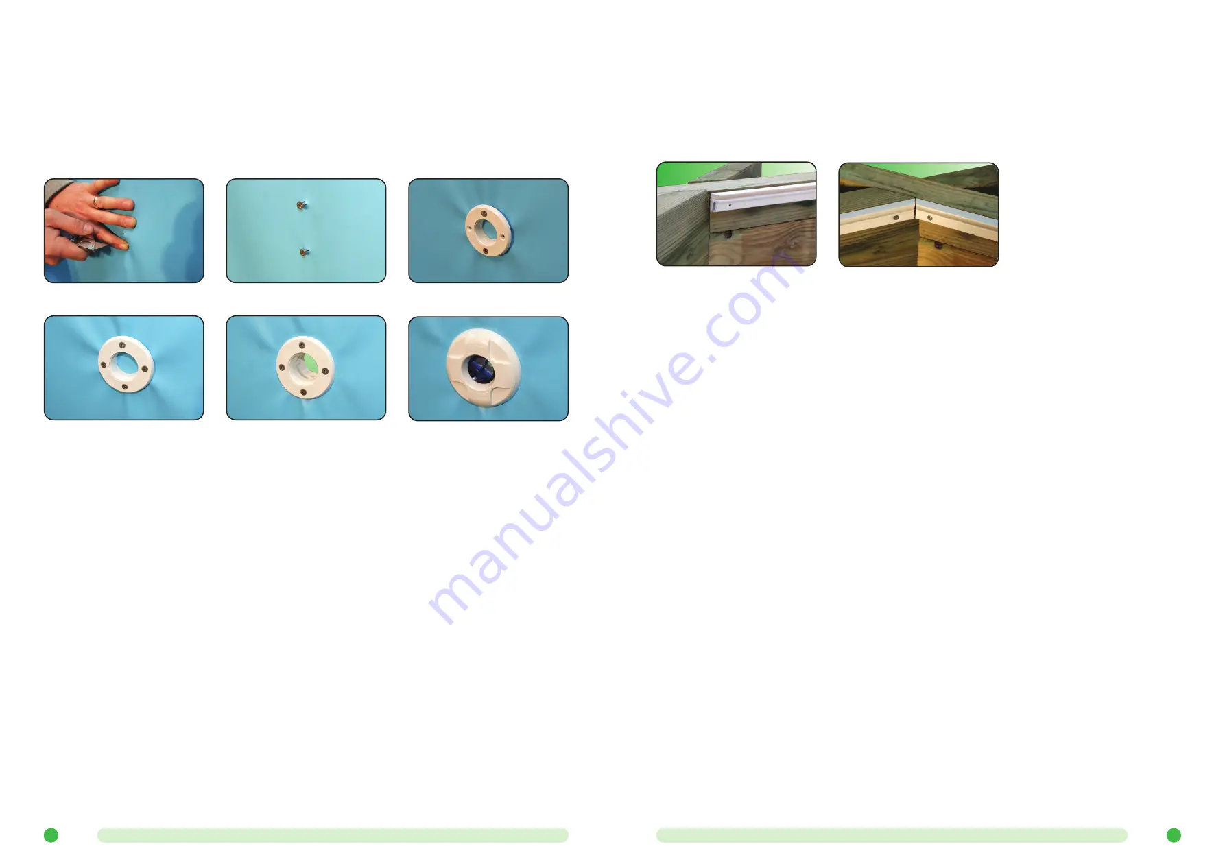
• Feel the position of the screws in the return flow fitting. Take a Stanley knife or similar and make two small cuts in a cross shape
on top of each screw head. Remember that you positioned the screw with the cross head in the 12, 3, 6 & 9 O’clock positions
and make the cuts so that your knife blade pierces the liner and goes into the screw head
[see figure 30]
.
• With finger tips surrounding the screw tension the liner evenly so that the screw head pops through the liner. It may be necessary
to increase the cut size on top of the screw head but keep these as small as possible
[see figure 31]
.
• Repeat this procedure for the second screw and then remove both screws.
• Loosely fit the return faceplate by replacing the screws just removed. Tighten these screws so the cone of the faceplate is just
starting to tension the liner
[see figure 32]
.
• Take the remaining two screws and using the premade screw holes in the faceplate as a guide pierce the liner with them and
tighten to just tension the liner all around
[see figure 33]
.
• Use your knife to cut out the neat circle of liner material that is outlined by the cone of the faceplate
[see figure 34]
.
• Tighten the screws evenly so that the faceplate is flat against the liner forming a water proof seal.
• Screw in the return faceplate and eyeball. Do not over tighten this
[see figure 35]
.
• Use the same method for the skimmer and optional light but note that these fittings often come with a second gasket which is
fitted between the liner and faceplate, e.g. on these fittings there is a gasket either side of the liner.
Figure 33
Figure 30
Figure 32
Figure 31
Figure 34
Figure 35


