8
Connection of compressed air
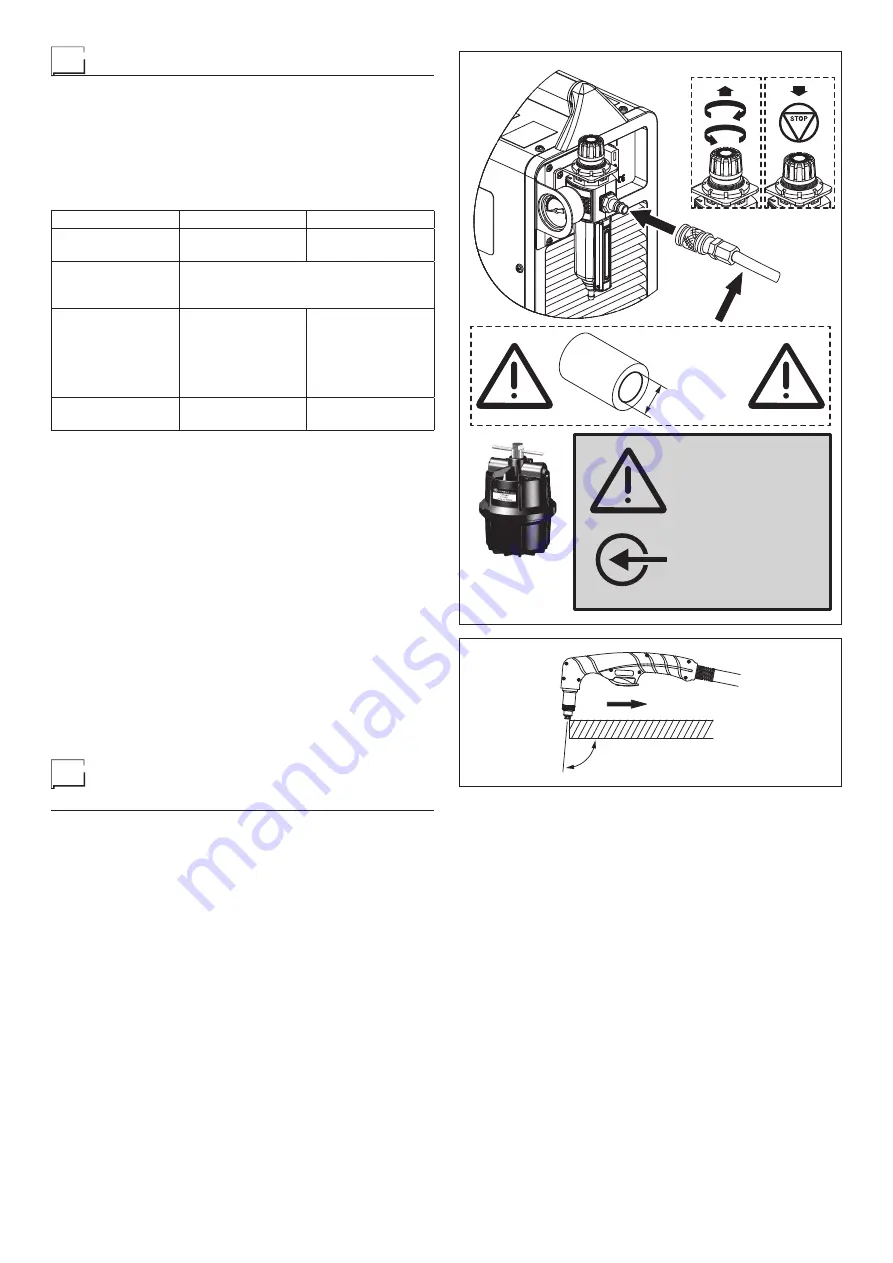
Connect the compressed air hose to the rapid coupling (Fig. D).
Use a compressed air hose with a minimum internal diame-
ter of 8 mm.
Make sure that the gas feed pressure does not exceed 8,6
bar / 861 kPa. If the pressure is higher than this value, the fil-
ter could explode.
The plant must be fed with a constant air flow, with the follow-
ing characteristics:
Equipment
SHARK 75
SHARK 105
Torch
SK 75
SKM 75
SK 125
SKM 125
Air / gas
AIR -
Clean, dry, oil-free for ISO 8573-1
Class 1.2.2
N
2
-
99.95%
Pressure
5,0-5,5 bar
72-80 psi
Cutting:
5,0-6,0 bar
72-87 psi
Gouging:
4,0-4,5 bar
58-65 psi
Flow rate
185 l/min
390 cfh
295 l/min
630 cfh
Having pressed the compressed air button (Pos. 7, Fig. B),
set the pressure regulator to obtain the value indicated on the
table above, by raising and then rotating the ring nut, as indi-
cated in figure D. Once regulation has been completed, low-
er the ring nut.
NOTE:
The pressure must be set with the pressure rising, while
the air / gas is flowing.
If the quality of the air / gas supply is not good, the cutting
speed diminishes, the cut quality worsens, the cuttable thick-
ness diminishes, and the working lifespan of consumables is
reduced.
If moisture, oil or other pollutants get into the air line, due to
the general compressor, use the additional CEA filtration sys-
tem, code 427529 (Fig. D) with a filtration grade of 0,01 μinch
- 0,25 μm available via CEA PLASMATECH distributors (the
order code for replacement filters is 427530).
The additional filtration system must be installed between the
air / gas supply and the filter located on the generator’s back
panel. Additional filtration could increase the minimum feed
pressure required.
Sequence of operations to
perform before cutting
IMPORTANT:
Before switching on the equipment follow these
instructions carefully:
• Make sure the voltage and frequency of the supply network
correspond to the data on the rating plate.
• Make sure all the torch components are correctly installed.
• Do not point the torch toward yourself or other persons near-
by. If switched on accidentally the pilot arc spark would ignite
and cause dangerous burns.
1) Turn the main switch (Pos. 5, Fig. A) to 1.
2) Check that the green LED (Pos. 11, Fig. B) on the front of
the machine is on.
3) Push the testing button for initial airflow adjustment (Pos. 7,
Fig. B) upward: air will come out of the torch for about 1
minute.
4) Check that the green AIR CHECK LED switches on (Pos.
8, Fig. B) on the machine’s front panel.
5) Turn adjustment filter (Pos. 8, Fig. A) to adjust air pressure
until the pressure gauge (Pos. 9, Fig. A) reads 5.5 bar. After
about one minute, the air stops and the green AIR CHECK
LED (Pos. 8, Fig. B) switches off.
6) By pushing the cutting mode selection button (Pos. 6, Fig.
B), according to the corresponding lit LED, the operator
can select one of the following cutting modes:
• Solid material mode: when the torch button is pushed,
when the operator goes out of the workpiece during cut-
ting, the arc switches off automatically.
• Mesh material mode: when the torch button is pushed,
when the operator goes out of the workpiece during cut-
ting, the pilot arc ignites again automatically, to allow cut-
ting to continue.
7) Adjust the cutting current by turning the potentiometer
(Pos. 1, Fig. B). The digital amperometer will display the
set cutting current. Increasing the current will permit high-
er speed cutting or, at the same speed, cutting of greater
thi ckness.
8) Move the torch close to the workpiece (Fig. E) and, keep-
ing the shield supported without exerting pressure, push
the torch button, thereby igniting the pilot arc and the air
supply. Introduce the flame to the workpiece, and begin the
cut. Go with the flame to the piece and start cutting. The
red LEDs (Pos 9-10, Fig. B) are lit up during cutting oper-
ations. Do not keep the pilot arc in the air, to avoid need-
less consumption of the electrode and nozzle.
9) In special cases if the arc is switched off when the work-
piece enters, observe the correct angle of inclination be-
tween the torch and the metal (Fig. E). A special control
Ø ≥
8 mm
Aria compressa
Compressed air only
max 125 psi
(8.6 bar / 861 kPa)
ATTENZIONE
WARNING
427529
90-95°
FIG. D
FIG. E
Summary of Contents for SHARK 105
Page 45: ...45 Wiring diagram SHARK 75...
Page 46: ...46 Wiring diagram SHARK 105...


