background image

MB502 6” Deluxe Jointer


19


Fig. 45 

ADJUSTING TABLE GIBS 


“Gibs” are provided to take up all play between the mating dovetail ways of the base and 

the infeed and outfeed tables. The “gib” for the infeed table is shown at (A) Fig. 46, and 

the “gib” for the outfeed table is shown at (B) Fig. 47. Proper “gib” adjustment is necessary 

for the correct functioning of the jointer. The “gibs” were adjusted at the factory and should 

require no further adjustment. If, However, it becomes necessary to adjust the “gibs” 

proceed as follows. 


1.To adjust the infeed or outfeed table “gibs”, loosen three locknuts (F) Fig. 46, for the 

infeed table or two locknuts (G) Fig. 47, for the outfeed table. 


2. Tighten or loosen three gib adjustment screws (C) Fig. 46, as necessary for the infeed 

table or two gib adjustment screws (D) Fig. 47, as necessary for the outfeed table; starting 

with the lower screw first and as you proceed to the top screw, gently raise the outboard 

edge of the table that is being adjusted. This will offset any tendency for the table casting 

to “droop or sag” and permit the gib to be adjusted to a secure fit. After the gibs have been 

adjusted, tighten locknuts (F) Fig. 46, (G) Fig. 47. 


IMPORTANT:

 Do not leave the adjusting screws too loose. It should take a little bit of effort 

to move the tables up or down. Jointers are finishing machines and you cannot expect to 

get good accuracy or finish if the tables are set loose and sloppy. 


FENCE OPERATION 


The fence can be moved across the table and can tilt 45 degrees right or left at any 

position on the table as follows. 

 
1.  To move the fence across the table, loosen lock handle (A) Fig. 48, slide fence to the 

desired position on the table and tighten lock handle (A). As the fence is moved across 
the table, the rear cutterhead guard (B) covers and guards the cutterhead in back of 
the fence. 

NOTE:

 Lock handle (A) is spring-loaded and can be repositioned by pulling 

Summary of Contents for MB502

Page 1: ...OWNER S OPERATING MANUAL MB502 6 DELUXE JOINTER Please keep this instruction manual for future reference 带格式的 ...

Page 2: ... relative to a particular application DO NOT use the machine until you have first contacted your local dealer to determine if it can or should be performed on the product WARNING FAILURE TO FOLLOW THESE RULES MAY RESULT IN SERIOUS PERSONAL INJURY 1 FOR YOUR OWN SAFETY READ INSTRUCTION MANUAL BEFORE OPERATING THE TOOL Learn the tool s application and limitations as well as the specific hazards pecu...

Page 3: ...DISCONNECT TOOLS before servicing and when changing accessories such as blades bits cutters etc 18 USE RECOMMENDED ACCESSORIES The use of accessories and attachments not recommended by the local dealer may cause hazards or risk of injury to persons 19 REDUCE THE RISK OF UNINTENTIONAL STARTING Make sure switch is in OFF position before plugging in power cord 20 NEVER STAND ON TOOL Serious injury co...

Page 4: ...l rust and pitch 4 BEFORE starting machine check cutterhead guard to make sure it is not damaged and operates freely 5 ALWAYS make sure exposed cutterhead behind the fence is guarded especially when jointing near the edge 6 NEVER perform jointing or planning operations with the cutterhead guard removed 7 MAKE CERTAIN the infeed and outfeed tables are tightened before starting the machine 8 NEVER s...

Page 5: ...s etc 20 SHUT OFF power before servicing or adjusting jointer 21 DISCONNECT jointer from power source and clean the machine before leaving it 22 MAKE SUFE the work area is clean before leaving the machine 23 SHOULD any part of your jointer be missing damaged or fail in any way or any electrical component fail to perform properly shut off switch and remove plug from power supply outlet Replace miss...

Page 6: ...erhead Both hands exert pressure to keep the work in contact with the fence Fig 2 Planning Operations Planning or surfacing are identical to the jointing operation except for the position of the workpiece For planning the major flat surface of the workpiece is placed on the infeed table of the jointer with the narrow edge of the workpiece against the fence as shown in Fig 3 The workpiece is moved ...

Page 7: ... jointer and all loose items Fig 4 and Fig 5 illustrate the jointer and all loose items supplied with your machine Remove the protective coating from the table surface and all unpainted parts This coating may be removed with a soft cloth moistened with kerosene do not use acetone gasoline or lacquer thinner for this purpose After cleaning cover the table surface with a good quality paste wax Buff ...

Page 8: ... 36 Flat washers 8 for assembling stand and dust chute to stand 36 Carriage bolt M8x30 for assembling motor to dust chute 4 Hex nuts M8 for assembling motor to dust chute 4 Flat washers 8 for assembling motor to dust chute 4 Flat washers 10 for assembling motor to dust chute 4 Lock washers 8 for assembling motor to dust chute 4 Screws M5x16 for assembling switch box to stand 2 Hex nuts M5 for asse...

Page 9: ...his time IMPORTANT The top lips of two upper end braces A must fit on top of the top lips of two upper side braces B 2 Assemble four rubber feet F Fig 6 to the bottom of each leg E as shown Fig 6 ASSEMBLING DUST CHUTE TO STAND 1 The front of the stand is indicated by switch opening B Fig 7 making the outfeed end of the stand C and the infeed end A 2 Assemble dust chute D Fig 7 to outfeed end of st...

Page 10: ... inside of switch opening B refer to Fig 7 using the two 3 8 long screws and flat washers Fig 8 ASSEMBLING JOINTER TO STAND 1 WARNING JOINTER WEIGHTIS APPROXIMATELY 75KGS CARE MUST BE TAKEN WHEN LIFTING JOINTER ONTO STAND A MINIMUM OF TWO PEOPLE WILL BE REQUIRED TO LIFT THE MACHINE 2 The infeed end of the jointer is fastened to the two holes A Fig 9 and the outfeed end of the jointer is fastened t...

Page 11: ... CHUTE COVER W DUST COLLECTOR ADAPTER Assemble dust chute cover with dust collector adapter A Fig 10 to jointer stand using screws IMPORTANT Top of dust chute cover with dust collector adapter A must be inside top end brace D of stand and should completely cover the top of the dust chute WARNING During operation the dust chute cover with dust collector adapter A must always be assembled as shown a...

Page 12: ...tighten two setscrews 4 Correct belt tension is obtained when there is approximately 1 deflection at the center span of the belt using light finger pressure 5 If an adjustment is required for belt tension the motor can be raised or lowered to obtain the correct belt tension Then tighten motor mounting hardware after tension is applied making sure alignment of the pulleys is not disturbed 6 Replace...

Page 13: ...TE If fence does not slide in and out easily loosen two screws X Fig 14 and adjust bracket B Then tighten two screws X 2 Assemble rear cutterhead guard C Fig 15 to end of hexagon rod using the 5 8 long screw D and washer E Fig 15 3 Thread fence locking handle assembly F Fig 22 and flat washer G into hole Z Fig 21 Lock handle F Fig 22 is spring loaded and can be repositioned by pulling out the ...

Page 14: ...C 2 Assemble cutterhead guard C Fig 17 to the jointer by inserting post B down through the hole in the infeed table NOTE A spring is supplied in knob assembly D that returns the guard C over the cutterhead after a cut has been made Turn knob D to provide tension on the spring before inserting post B Make certain the spring engages in the slot of the post If spring tension is too much or too little...

Page 15: ...ed into a matching outlet that is properly installed and grounded in accordance with all local codes and ordinances 2 Do not modify the plug provided If it will not fit the outlet have the proper outlet installed by a qualified electrician 3 Improper connection of the equipment grounding conductor can result in a risk of electric shock The conductor with insulation having an outer surface that is ...

Page 16: ...event of a malfunction or breakdown grounding provides a path of least resistance for electric current to reduce the risk of electric shock This tool is equipped with an electric cord having an equipment grounding conductor and a grounding plug The plug must be plugged into a matching outlet that is properly installed and grounded in accordance with all local codes and ordinances Do not modify the...

Page 17: ... the machine ON push button I on switch A To turn the machine OFF push the button O on the switch A The magnetic switch is a no volt switch if power source is cut off accidentally you have to push the button I to restart the unit again Fig 19 OUTFEED TABLE ADJUSTMENTS For most jointing operations the outfeed table must be exactly level with the knives at their highest point of revolution This mean...

Page 18: ...hould just touch the straight edge 4 If the knife is high or low at either end slightly turn the four screws in the knife locking bar clockwise to loosen using the wrench Then adjust the height of the knife by turning the knife raising screws counterclockwise to lower and clockwise to raise the knife NOTE If the knife is to be lowered it will be necessary to carefully push down on the knife after ...

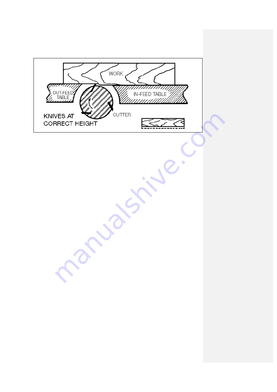
Page 19: ...are set too high the work will be gouged at the end of the cut as shown in Fig 44 Fig 44 8 As a final check run a piece of work slowly over the knives for 6 to 8 inches The wood should rest firmly on both tables as shown in Fig 45 with no open spaces under the finished cut ...

Page 20: ...h the lower screw first and as you proceed to the top screw gently raise the outboard edge of the table that is being adjusted This will offset any tendency for the table casting to droop or sag and permit the gib to be adjusted to a secure fit After the gibs have been adjusted tighten locknuts F Fig 46 G Fig 47 IMPORTANT Do not leave the adjusting screws too loose It should take a little bit of e...

Page 21: ...nd 45 degree angle to the table in the inward or outward position To check and adjust the positive stops proceed as follows 1 Position the fence at 90 degrees to the table Make certain the end of plunger A Fig 50 is engaged in notch B in index collar as shown and tighten lock handle C 2 Place a square D Fig 51 on the table and against the fence and check if fence is 90 degrees to table 3 If an adj...

Page 22: ...nch A Fig 57 slightly loosen the four locking screws B in each knife slot by turning the screws B clockwise This relieves stress in the cutterhead 4 Loosen screws B Fig 57 further and remove knife and knife locking bar 5 Fig 58 illustrates the knife C and knife locking bar D removed from the cutterhead Remove the remaining two knives and locking bars in the same manner 6 Using wrench E Fig 58 lowe...

Page 23: ...the infeed table and place a straight edge J Fig 61 on the outfeed table extending over the cutterhead as shown 14 Rotate the cutterhead by hand until the knife is at its highest point at each end of the cutterhead To raise the knife use wrench E Fig 61 and turn raising screw clockwise until the knife just touches the straight edge J on each end and center of the cutterhead when the knife is at it...

Page 24: ...el of the knife as shown Hold the cutterhead from turning and whet the beveled edge of the knife stroking lengthwise by sliding the stone back and forth across the table Do the same amount of whetting on each of the three knives REMOVING DUST CHUTE COVER The dust chute cover A Fig 63 can be removed for cleaning purposes by removing the two wing screws B WARNING MAKE CERTAIN THE MACHINE IS DISCONNE...

Page 25: ... in Fig 64 The left hand should then be moved to the work on the outfeed table at the same time maintaining flat contact with the fence The right hand presses the work forward and before the right hand reaches the cutterhead it should be moved to the work on the outfeed table Fig 64 CAUTION NEVER PASS HANDS DIRECTLY OVER THE CUTTERHEAD JOINTING AN EDGE This is the most common operation for the joi...

Page 26: ...MB502 6 Deluxe Jointer 2 Fig 65 DO NOT PERFORM JOINTING OPERATIONS ON MATERIAL SHORTER THAN 10 INCHES NARROWER THAN 3 4 INCH OR LESS THAN 1 2 INCH THICK REFER TO FIG 66 Fig 66 ...

Page 27: ...o cut a bevel lock the fence at the required angle and run the work across the knives while keeping the work firmly against the fence and tables Several passes may be necessary to arrive at the desired result When the angle is small there is little difference whether the fence is tilted to the right or left However at greater angles approaching 45 degrees it is increasingly difficult to hold the w...

Page 28: ...fect is to plane off all the stock in front of the knives to increasing depth leaving a tapered surface The ridge left by the knives when starting the taper may be removed by taking a very light cut according to the regular method for jointing with the infeed table raised to its usual position Practice is required in this operation and the beginner is advised to make trial cuts on waste material T...

Page 29: ... depth of cut when rebating with this jointer is 1 2 inch PLANING WARPED PIECES If the wood to be planed is dished or warped take light cuts until the surface is flat Avoid forcing such material down against the table excessive pressure will spring it while passing the knives and it will spring back and remain curved after the cut is completed PLANING SHORT OR THIN WORK When planning short or thin...

Page 30: ...r 2 Fig 70 Fig 71 DIRECTION OF GRAIN Avoid feeding work into the jointer against the grain as shown in Fig 72 The result will be chipped and splintered edges Feed with the grain as shown in Fig 73 to obtain a smooth surface ...

Page 31: ...MB502 6 Deluxe Jointer 3 Fig 72 Fig 73 ...

Page 32: ...MB502 6 Deluxe Jointer 1 ...

Page 33: ...over 1 63 Screw 6 64 Screw 4 65 Base 1 66 Dust Chute 1 67 Dust Chute Label 1 68 Cover Plate 1 69 Bolt 4 Item Description Q ty 72 Wing Screw 2 73 Bolt 36 74 Motor Base 1 76 Washer 4 77 Nut 4 78 Pulley 1 79 Key 1 80 Screw 2 81 Washer 4 83 Pulley Cover 1 85 Motor 1 86 V Belt 1 87 Washer 36 90 Base 1 91 Knob 1 92 Knob Bar 1 93 Screw 2 94 Washer 2 95 Saddle Washer 2 96 Fence 2 97 Locking Handle 1 98 Up...

Page 34: ......

Reviews: