6
3. Hardware Introduction
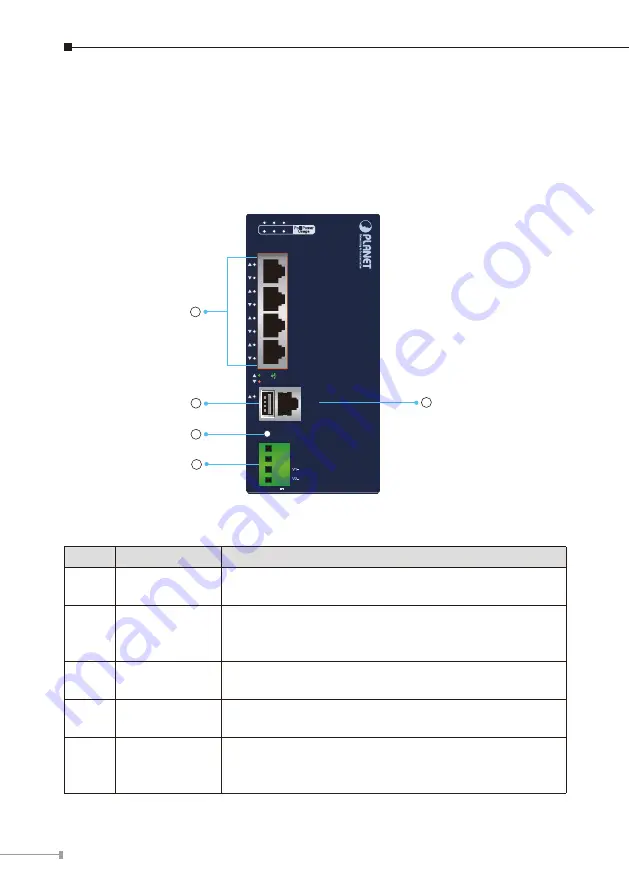
3.1 Front Panel
The front panel of the BSP-360 consists of 5 auto-sensing 10/100/1000Mbps
Ethernet RJ45 ports and one USB interface. The LED Indicators are also located on
the RJ45 ports of the BSP-360.
V1+
Reset
V2+
BSP-360
PWR Alarm PV System
50W 100W 120W
1
2
3
4
5/WAN
PoE Power
Usage
ACT
LNK
PoE-in-Use
Industrial Renewable Energy
Managed PoE+Switch/Router
DC Ouput: 24V , 2A max.
1
2
3
4
5
Figure 3-1
Front Panel of BSP-360
Item
Interface
Description
1
Port-1~Port-4
4 10/100/1000BASE-T RJ45 auto-MDI/MDI-X ports with
802.af/at PoE+
injector function.
2
Port-5
One 10/100/1000BASE-T RJ45 auto-MDI/MDI-X port.
Port-5 functions as
WAN
port when the operation
mode of BSP-360 is configured to
“Gateway mode”.
3
USB
Connect the USB storage to USB port and back up the
configuration file.
4
Reset Button
< 5 seconds: System reboot.
> 10 seconds: Factory default.
5
4-pin Terminal
Block
2 x 24V 2A DC output
connector.
The output voltage is the same as battery voltage.
Maximum power output is clamped at 48W.
Summary of Contents for BSP-360
Page 24: ......


