background image


4


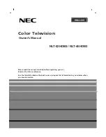
When you want to close the base and body to 90°, you need 
to release a button from 25°. (See fig. 1-6) 


Figure 1-6


Warning: 

Do not force the LCD Monitor over its maximum viewing angle settings as stated above. Attempting 

this will result in damaging the Monitor and Monitor stand.


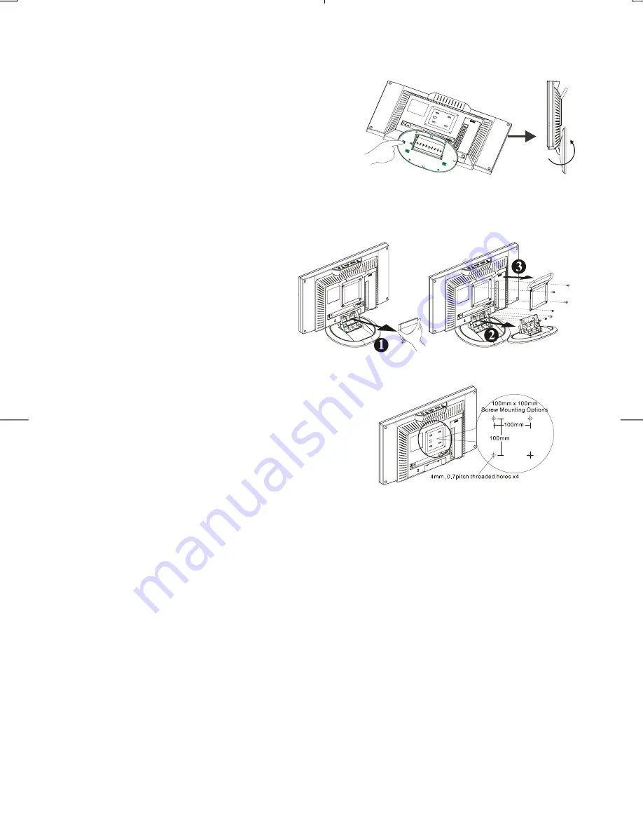
1.7 Detaching main body from Its Stand 

1. Remove the rear cover from neck   (See 

Figure 1-7) 

2. Unscrew screws of the hinge bracket   
3. Remove the stand from main body 


Figure 1-7


1.8 Interface for Arm Applications   

Before installing to mounting device, please refer to Fig.1-7 
The rear of this LCD display has four integrated 4 mm, 0.7 
pitches threaded nuts, as well as four 5 mm access holes in 
the plastic covering as illustrated in Figure 1-8. These 
specifications meet the VESA Flat Panel Monitor Physical 
Mounting Interface Standard (paragraphs 2.1 and 2.1.3, 
version 1, dated 13 November 1997).


Figure 1-8


Note :Please using Ø 4mm x 8mm (L) screw for this application.

Summary of Contents for XP17W

Page 1: ......

Page 2: ...gineered and manufactured with the highest priority on safety However improper use can result in electric shock and or fire In order to prevent potential danger please observe the following instructio...

Page 3: ...uct is in proper operating condition Polarization This AC adapter may be equipped with a polarized alternating current line plug a plug having one blade wider than the other This plug will fit into th...

Page 4: ...ircumstance Full screen true color display TV systems NTSC system Built in TV tuner for receiving terrestrial or cable TV Easy operation With one button to switch signals coming from composite VIDEO S...

Page 5: ...Unscrew screws of the hinge bracket 3 Remove the stand from main body Figure 1 7 1 8 Interface for Arm Applications Before installing to mounting device please refer to Fig 1 7 The rear of this LCD d...

Page 6: ...n for selecting PC mode 6 Volume Lower Raise the sound volume TV AV mode OSD function for adjusting PC mode 7 Source Selection CABLE TV AV 1 S VIDEO AV 2 C VIDEO or PC 2 1 2 Rear view of main body Fig...

Page 7: ...ease turn off the power of all devices before connection For audio connection please use RCA audio L R connector For video connection please choose either RCA video connector or s video connector More...

Page 8: ...7 Chapter 3 Operation Instruction 3 1 IR Control...

Page 9: ...increase or decreases the brightness of the image PICTURE To increase or decreases the contrast of the image COLOR Lower color or higher color intensity HUE Toward purple or green adjusting SHARP Adju...

Page 10: ...ody or on remote control to enter second page There are five options to set the PIP preference SOURCE To select the video source from TV AV1 AV2 or to turn off PIP mode AUDIO To select sound from PC M...

Page 11: ...function is to choose 4 scales size for picture H Pos This function is to move the video window left or right V Pos This function is to move the video window up or down OSD H Position This function mo...

Page 12: ...rity Positive Negative Amplitude 0 0 7 0 05 Vp Multi mode Supported Horizontal Frequency 30 60 KHz Vertical Frequency 50 75 Hz Speaker 2 5W 4 5 OHM Control Power switch hard and soft types On Off swit...

Page 13: ...ack Environment Operating Condition Temperature 5 C to 40 C 41 F to 104 F Relative Humidity 20 to 85 Storage Condition Temperature 20 C to 60 C 4 F to140 F Relative Humidity 5 to 85 Power Supply AC In...

Page 14: ...68 75Hz 1312x800 60 023 P 75 029 P 78 750 IBM MODES DOS 720x400 70Hz 900 x 449 31 469 N 70 087 P 28 322 DOS 640x350 70Hz 800 x 449 31 469 P 70 087 N 25 175 Note When the in put display mode is not 128...

Page 15: ...on the LCD Monitor is ON all connections are secured and the system is running on the correct timing Refer to Chapter 3 for information on timing 2 Turn off the LCD Monitor and then turn it back on ag...

Reviews: