78
5.1 Troubleshooting Tips
Margay has several troubleshooting aids.
On Screen codes
The On Screen code is a series of red and amber
lights that can flash on the screen to tell you what is
wrong. These flashing lights are particularly helpful
when the lamp won’t light.
See 5.2 “Reading the On Screen Code” on page 80.
Inside LEDs
The LEDs on the electronics module give you
information about the state of the Margay.
See 5.3 “Reading the LEDs” on page 82.
General troubleshooting
Exchange parts
from one display to another. This is a
very effective way to find a problem. If the problem
follows the part to the new unit, that part was at
fault.
If the problem stays in the first unit, you haven’t
found the problem yet, but you have learned some-
thing: The part you move was not the problem. Put it
back in the original unit and try something else.
Lamp won’t light
Check to make sure the lamp is actually
not
lit. If
the lamp is lit, you can usually see light if you look
carefully. Light may come through spaces between
parts
Many things can make the screen black, even
though the lamp is lit.
• The Curtain may be on. If the curtain is black and
it is on, the screen will be black.
• There is no source picture. With no valid picture
coming in, the display will be black.
• There is something blocking the light to the
screen. Is the lens cap on?
• There are parts missing in the optical path. If
someone was working on the display, maybe he or
she forgot to put something back in.
If the lamp is not lit:
• No AC coming in? Check the main AC switch on
the display. It should be lit.
• No ballast power? Some displays have a green
LED near the main AC switch that lights when
the 350 volt part of the power supply is working.
It should be lit. Other displays may have an LED
on the electronics module to show when this high
voltage power is available.
WARNING
Always turn off the AC power and remove the
power cord before working inside the display
and before removing a lamp.
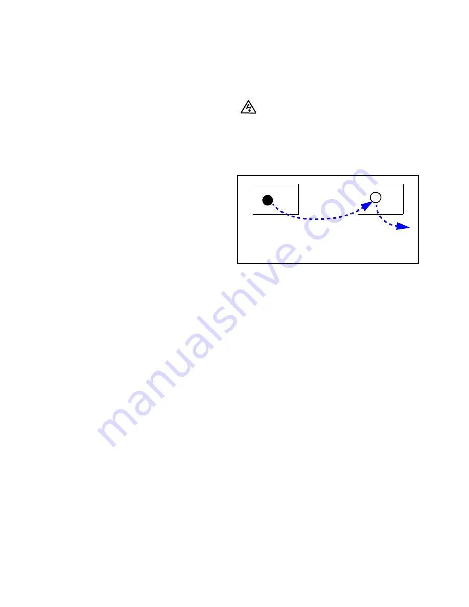
• If you have AC and ballast or 350V power, try
swapping the lamp into a display where the lamp
is good.
a. If Lamp A works in Display B, put it back in
Display A. Lamp A is OK.
b. If Lamp A does not work in Display B, the
problem is Lamp A. Put a new lamp in
Display A.
• If the lamp is OK, try swapping the ballast in the
same way. The lamp ballast provides power to the
lamp. It is an electronic part, and all electronic
parts are eventually subject to failure.
• Fan failed. Most fans are sensed. That means the-
electronics module knows whether they are run-
ning or not. If they don’t run when they should,
the electronics module turns off the lamp and pre-
vents it from striking (turning on) again.
Swapping other parts
You can swap electronics modules or fans in the
same way to see if one is bad.
When you swap electronics modules, try to put
them back in their original locations. Otherwise you
may have to do setup procedures again, such as Input
Level adjustment and Color Balance, because these
values are stored in the electronics module.
When you swap fans, always exchange fans of the
same size.
Why not use a new part out of the box?
It may seem like a good idea to take a new part out
of the box and substitute it for a suspected part in the
Lamp A doesn’t
work here.
Move Lamp A
here.
Move good Lamp B
out temporarily.
Display A
Display B
Summary of Contents for WN-5040-720
Page 1: ...WN 5040 720 User Guide...
Page 2: ......
Page 3: ...i WN 5040 720 Margay 50 Display Wall Unit User Guide 020 0548 00B 29 March 2007...
Page 6: ...iv...
Page 7: ......
Page 14: ...5...
Page 17: ...6...
Page 20: ...9...
Page 24: ...13...
Page 30: ...19...
Page 32: ...21 Electronics module as seen from the front The electronics module door is open...
Page 34: ...23 In Out...
Page 36: ...25...
Page 38: ...27 AC power in and out 1 4 5 3 2 6 No more than 4 115 VAC...
Page 40: ...29...
Page 51: ...40...
Page 54: ...43...
Page 56: ...45...
Page 58: ...47...
Page 66: ...55...
Page 70: ...59...
Page 72: ...61...
Page 74: ...63 ENTER ENTER...
Page 77: ...66...
Page 80: ...69...
Page 82: ...71...
Page 84: ...73...
Page 86: ...75...
Page 95: ...84...
Page 115: ...104 Diagnostics RS232 RS485 Status...
Page 116: ...105 Diagnostics Test Patterns...
Page 117: ...106 Diagnostics Setup Summary...
Page 128: ...117 Starts scanning the input con nectors for the next available source...
Page 131: ...120 7 3 Drawings All dimensions are in inches...
Page 132: ...121...
Page 133: ...122...
Page 134: ...123...
Page 140: ...129...
Page 144: ...133...


