background image

22

               PT191MU User’s Guide (020-0418-00 A)

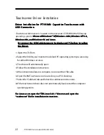
Touchscreen Driver Installation

Dr

Dr

Dr

Dr

Driv

iv

iv

iv

iver I

er I

er I

er I

er Installa

nstalla

nstalla

nstalla

nstallation f

tion f

tion f

tion f

tion for PT191MU: C

or PT191MU: C

or PT191MU: C

or PT191MU: C

or PT191MU: Capacitiv

apacitiv

apacitiv

apacitiv

apacitive 

e  T

T

T

T

Touchscr

ouchscr

ouchscr

ouchscr

ouchscreen with

een with

een with

een with

een with

USB Connection.

USB Connection.

USB Connection.

USB Connection.

USB Connection.

Touch driver information is located on the enclosed CD-ROM for the following
operating systems: M

M

M

M

Micr

icr

icr

icr

icrosof

osof

osof

osof

osoft 

t W

W

W

W

Windo

indo

indo

indo

indow

w

w

w

ws® XP

s® XP

s® XP

s® XP

s® XP, 

, , 

, , W

W

W

W

Windo

indo

indo

indo

indow

w

w

w

ws 2000, 

s 2000, 

s 2000, 

s 2000, 

s 2000, W

W

W

W

Windo

indo

indo

indo

indow

w

w

w

ws NT 4.0,

s NT 4.0,

s NT 4.0,

s NT 4.0,

s NT 4.0,

Windows Me, and Windows 9X and Linux.

Windows Me, and Windows 9X and Linux.

Windows Me, and Windows 9X and Linux.

Windows Me, and Windows 9X and Linux.

Windows Me, and Windows 9X and Linux.

Disconnect the USB Cable between the display and PC before installing

Disconnect the USB Cable between the display and PC before installing

Disconnect the USB Cable between the display and PC before installing

Disconnect the USB Cable between the display and PC before installing

Disconnect the USB Cable between the display and PC before installing
the Dr

the Dr

the Dr

the Dr

the Driv

iv

iv

iv

iver

er

er

er

er.....

1. Open the CD-Rom.

2. Select the link for your monitor model and PC operating system you are using

for either Windows or Linux.

3. The driver will automatically open.

4. Follow the installation instructions.

5. When driver installation is complete, reconnect the USB cable.

6. Open the 3M Touchware icon located on your PC‘s desktop.

7. Select the “Calibrate” tab and follow the calibration instructions.

8. If the touchscreen driver does not automatically load, restart the computer

operating system.

F

FF

F

For Linux users open the 

or Linux users open the 

or Linux users open the 

or Linux users open the 

or Linux users open the “““““T

T

T

T

TWLinux 5.62.1”

WLinux 5.62.1”

WLinux 5.62.1”

WLinux 5.62.1”

WLinux 5.62.1” dir

 dir

 dir

 dir

 direc

ec

ec

ec

ectttttor and open the

or and open the

or and open the

or and open the

or and open the

“readme.txt” file for installation instructions.

“readme.txt” file for installation instructions.

“readme.txt” file for installation instructions.

“readme.txt” file for installation instructions.

“readme.txt” file for installation instructions.

Summary of Contents for PT191MU

Page 1: ...PT191MU Touchscreen Monitor USER S GUIDE www planar com...

Page 2: ...reen 5 Package Overview 6 I I I I Installa nstalla nstalla nstalla nstallation tion tion tion tion ProductOverview 7 StartYourInstallation 10 User Controls User Controls User Controls User Controls Us...

Page 3: ...isconnect the power plug from AC outlet if the product is not used for a long period of time D D D D Don on on on on t t t t t Do not touch the LCD panel surface with sharp or hard objects Do not use...

Page 4: ...resolution 16 7 million displayable colors 31 5 80 kHz horizontal scan 56 75 Hz high refresh rate 0 294 mm x 0 294 mm pixel pitch 250 cd m2 typ brightness 4 CCFT backlight lamps w 50 000 hrs life 1000...

Page 5: ...uchscreen for PT191MU Surface Anti glare treatment Interface USB Durability Capacitive 225millionactivations Hardness of surface Capacitive 6 5 Mohs Transmittance Up to 88 typical S W Driver Compatibi...

Page 6: ...User s Guide 020 0418 00 A Package Overview LCD Display VGA Signal Cable USB Upstream Cable Power Adapter DVI D Cable Power Cord Audio In Cable User s Guide Landing Strip Touchscreen Driver Installati...

Page 7: ...ide 020 0418 00 A 7 Installation Product Overview F F F F Fr r r r ron on on on ont t t t t V V V V View iew iew iew iew R R R R Rear ear ear ear ear V V V V View iew iew iew iew LCD Display Front Pan...

Page 8: ...1 USB Downstream Ports 1 USB Downstream Ports 1 USB Downstream Ports ThesetwoUSBportsareavailableforconnectingUSBtypeperipheral devices such as keyboard mouse printer and so on 2 USB Upstream Port 2 U...

Page 9: ...nterfaceforflatpanel monitors andcorrespondingstandardsforflatpanelmonitormountingdevices such as wall and table arms The VESA mounting interface is located on the back ofyourmonitor Tomountthemonitor...

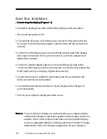
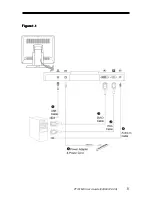
Page 10: ...erand tighten the screws 2 4 For the PC with DVI digital output Connect the DVI signal cable to the connector of the display card in your computer connect the other side to the DVI Dinputportofyourdis...

Page 11: ...PT191MU User s Guide 020 0418 00 A 11 F F F F Figur igur igur igur igure 1 1 e 1 1 e 1 1 e 1 1 e 1 1...

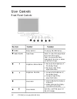
Page 12: ...s of the display image 2 Decreases value of the adjustment items 1 Increases the brightness of the display image 2 Increases value of the adjustment items 1 Green indicates the display is turned on 2...

Page 13: ...p the on screen menu and to select between the four main menus 2 Choosetheadjustmentitemsbypressing the SELECT AUTO button 3 Adjust the value of the adjustment items by pressing the _ or button 4 Once...

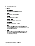
Page 14: ...izontal Position Horizontal Position Changesthehorizontalpositionoftheimage Vertical Position Vertical Position Vertical Position Vertical Position Vertical Position Changes the vertical position of t...

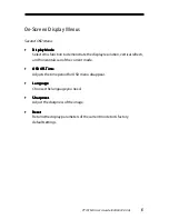
Page 15: ...horizontal scan of the current mode OSD O OSD O OSD O OSD O OSD Off ff ff ff ff T T T T Time ime ime ime ime AdjuststhetimeperiodforOSD menu disappear Language Language Language Language Language Cho...

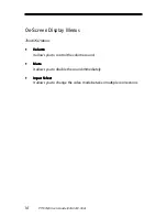
Page 16: ...Volume Volume Volume Volume Volume It allows you to control the volume sound Mute Mute Mute Mute Mute Itallowsyoutodisablethesoundimmediately Input Select Input Select Input Select Input Select Input...

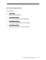
Page 17: ...Red Color Adjustment Red Color Adjustment Red It allows you to adjust the red color of the display Color Adjustment Green Color Adjustment Green Color Adjustment Green Color Adjustment Green Color Adj...

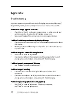
Page 18: ...g line bars Problem Image has vertical flickering line bars Problem Image has vertical flickering line bars Problem Image has vertical flickering line bars Problem Image has vertical flickering line b...

Page 19: ...ive any signal from the computer graphic card Check all the power switches power cables and VGA signal cable Going to Sleep Going to Sleep Going to Sleep Going to Sleep Going to Sleep This message mea...

Page 20: ...20 PT191MU User s Guide 020 0418 00 A Product Dimensions...

Page 21: ...800 x 600 800 x 600 1024 x 768 1024 x 768 1024 x 768 1280 X 1024 1280 X 1024 640 x 480 640 x 480 832 x 624 1024 x 768 70 70 70 60 72 75 56 60 72 75 60 70 75 60 75 67 67 75 75 31 5 31 5 31 5 31 5 37 9...

Page 22: ...display and PC before installing Disconnect the USB Cable between the display and PC before installing Disconnect the USB Cable between the display and PC before installing Disconnect the USB Cable be...

Page 23: ...PT191MU User s Guide 020 0418 00 A 23...

Page 24: ...271 Email Email Email Email Email PlanarSupport planar com Hours Hours Hours Hours Hours M F 5am 5pm Pacific Time 2005 Planar Systems Inc 03 05 Planar Systems Inc 03 05 Planar Systems Inc 03 05 Planar...

Reviews: