background image


Start Your Installation 


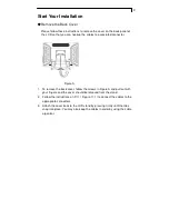
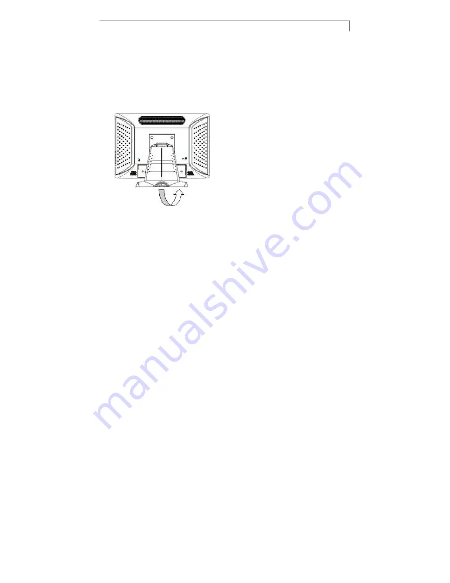
Remove the Back Cover 

      Please follow these instructions to remove the cover on the back panel of   

the LCD so that you can hookup the cables to associated connector. 


Figure A. 

1.  To remove the back cover, follow the arrows in Figure A and pull out with 

your fingers and the cover should be removed from the stand. 

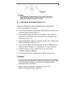
2.  Follow the instructions on P. 11


( Figure 11.1 ) to connect the cables to the 

appropriate connectors. 

3.  Attach the cover back to the LCD stand by pressing firmly until the tabs 

snap into place. You may also keep the cables in order by using the cable 

organizer. 


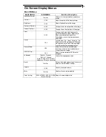
Summary of Contents for PT1910MX

Page 1: ...PT1910MX PT1915MU Touch Screen LCD Monitors USER S GUIDE www planar com...

Page 2: ...contain other electronic waste that can be hazardous if not disposed of properly Recycle or dispose in accordance with local state or federal Laws For more information contact the Electronic Industrie...

Page 3: ...roduct Overview 6 VESA Mount for your Monitor 8 Start Your Installation 9 Connecting the Display 10 User Controls Front Panel Controls 12 How to Use the OSD Menus 13 On Screen Display Menus 14 Appendi...

Page 4: ...ommercial cleaners or 50 50 mixture of water and isopropyl alcohol Use a soft cloth moistened with mild detergent to clean the display housing Use only high quality and safety approved AC DC adapter D...

Page 5: ...gy 1280x1024 SXGA resolution 19 viewable display area 31 5 80 kHz horizontal scan 56 75 Hz high refresh rate 0 294mm x 0 294mm Pixel pitch Auto adjustment function Multilingual OSD user controls VESA...

Page 6: ...rubber tipped pen with a 1 mm diameter minimum and a hardness of 60 degree Transmittance 80 2 Driver Windows VISTA XP 2000 ME 98 CE XP Embedded Linux Apple Mac OS Touch Screen for PT1915MU Surface Aco...

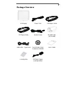
Page 7: ...w LCD Display Power Cord VGA Signal Cable DVI Signal Cable Audio in Cable RS 232 Cable PT1910MX USB Cable Type A to B Touch Screen Driver Installation CD ROM User s Guide Landing Strip DC Power Supply...

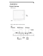
Page 8: ...6 Installation Product Overview Front View PT1910MX Bottom View Without Stand...

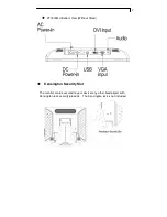
Page 9: ...PT1915MU Bottom View Without Stand Kensington Security Slot The monitor can be secured to your desk or any other fixed object with Kensington lock security products The Kensington lock is not include...

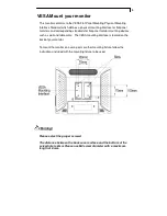
Page 10: ...itor mounting devices such as wall and table arms The VESA mounting interface is located on the back of your monitor To mount the monitor on a swing arm or other mounting fixture follow the instructio...

Page 11: ...A 1 To remove the back cover follow the arrows in Figure A and pull out with your fingers and the cover should be removed from the stand 2 Follow the instructions on P 11 Figure 11 1 to connect the c...

Page 12: ...play to the Audio out port of your computer 11 1 5 Connect the RS 232 or USB cable from the RS 232 or USB port of your display to the RS 232 port 11 1 or USB port 11 1 of your computer 6 Configure the...

Page 13: ...11 Figure 11 1...

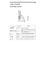
Page 14: ...m OSD menus Auto To activate the Auto Adjustment function to obtain an optimum image Brightness Minus Minus 1 Decreases the brightness of the display image 2 Decreases value of the adjustment items Br...

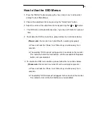
Page 15: ...ote the monitor has to be ON with a valid signal preset a Press and hold the Power and Menu key simultaneously for 4 seconds b The wording OSD Locked will appear for 4 seconds on the monitor This indi...

Page 16: ...djustment Phase 0 63 Synchronizes the signal timing of the displaytothat ofthegraphiccard Whenyou are experiencing vertical flickering image use this function to makeanadjustment Display Mode ADJ Sele...

Page 17: ...onfigure the resolution of your computer to make it less than or equal to 1280 x 1024 Problem Image has vertical flickering line bars Use Clock to make an adjustment Check and reconfigure the display...

Page 18: ...it cannot receive any signal from the computer graphics card Check all the power switches power cables and VGA DVI signal cable Going to sleep The LCD is under the power saving mode in addition the L...

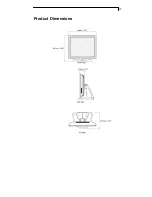
Page 19: ...17 Product Dimensions...

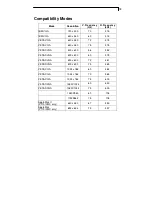
Page 20: ...5 VESA SVGA 800 x 600 56 35 2 VESA SVGA 800 x 600 60 37 9 VESA SVGA 800 x 600 72 48 1 VESA SVGA 800 x 600 75 46 9 VESA XGA 1024 x 768 60 48 4 VESA XGA 1024 x 768 70 56 5 VESA XGA 1024 x 768 75 60 0 V...

Page 21: ...both RS232 and USB connections The touch driver is located on the enclosed CD ROM for these OS Windows VISTA 64 32 bits XP 2000 ME 98 XP Embedded Linux WinCE NET If you are using RS232 connection foll...

Page 22: ...at USB cable is connected to the computer 2 Power on the computer 3 Load the touch screen driver CD 4 Follow the step by step instructions as shown on pop up windows PT1915MU Driver Install The touch...

Page 23: ...monitor touch screen or other Planar products visit our online store at www PlanarOnline com or find other stores who carry Planar products at http www planar com howtobuy Technical Support Visit Plan...

Page 24: ...866 PLANAR1 866 752 6271 or 1 503 748 5799 outside the United States Hours 24 hours a day 7 days a week 2008 Planar Systems Inc 1 08 Planar is a registered trademark of Planar Systems Inc Other brand...

Reviews: