background image

Safety Information

PS5580 Installation Guide

2

Safety Information

This display was designed with safety in mind. If you don’t heed the safety warnings 

and cautions, you could get hurt. The safety warnings are on stickers in various places 
in and on the display.

1

Read these instructions.

2

Keep these instructions.

3

Heed all warnings.

4

Follow all instructions.

5

Do not use any of the Planar PS5580 products near water.

6

Do not install near any heat sources such as radiators, heat registers, stoves or 
other apparatus (including amplifiers) that produce heat.

7

Do not defeat the safety purpose of the polarized or grounding type plug. A 
polarized plug has two blades with one wider than the other. A grounding 
type plug has two blades and a third grounding prong. The wide blade or the 
third prong is provided for your safety. When the provided plug does not fit 
into your outlet, consult an electrician for the replacement of the obsolete 
outlet.

8

Protect the power cord from being walked on or pinched particularly at plugs, 
convenience receptacles and the point where they exit from any of the Planar 
PS5580 products. 

9

Only use the attachments/accessories specified by the manufacturer.

10

Unplug all Planar PS5580 products during lightning storms or when unused 
for long periods of time.

11

You must follow all National Electrical Code regulations. In addition, be aware 

of local codes and ordinances when installing your system.

12

Refer all servicing to qualified service personnel. Servicing is required when 
any of the Planar PS5580 displays have been damaged in any way, such as the 
AC power cord or plug is damaged, liquid has been spilled or objects have 
fallen into the display, or if the displays have been exposed to rain or 
moisture, do not operate normally or have been dropped.

13

Keep the packing material in case the equipment should ever need to be 
shipped.

Summary of Contents for PS5580

Page 1: ...Planar PS5580 Installation Guide...

Page 2: ...great support display uptime and performance optimization From post sale technical support to a full suite of depot services our services are performed by trained Planar employees When you purchase a...

Page 3: ...king and Checking Display Accessories 8 Installing PS5580 Displays on VESA Mounts 10 Intermediate Rows 10 Last Top Row 11 Removing a panel 11 Connecting Cables 12 Parts of the Display 12 Input Ports 1...

Page 4: ...Setup A Menu 23 Setup B Menu 24 Options 25 Color Balancing the Wall 26 Color Temperature 26 Supported Input Signal Resolution 27 Specifications 29 Dimensions 30 Regulatory Information 31 Customer Sup...

Page 5: ...l describes how to use the PS5580 and gives notes on its use Please read the manual carefully before using this display If you have any questions or problems please contact Planar technical support ht...

Page 6: ...ovided plug does not fit into your outlet consult an electrician for the replacement of the obsolete outlet 8 Protect the power cord from being walked on or pinched particularly at plugs convenience r...

Page 7: ...displays mounts brackets and cables 15 Slight pressure on the LCD will cause distortion of the image Heavier pressure will cause permanent damage Planar PS5580 configurations should be mounted in a wa...

Page 8: ...l ventilation openings or fans must be provided to keep the internal temperature between 0 35 C 32 95 F For grounding the PS5580 and attached devices it should be connected as a frame ground Consideri...

Page 9: ...Recommended Operating Conditions PS5580 Installation Guide 5 European Disposal Information...

Page 10: ...warranty terms and conditions for details Here are some guidelines to help you avoid TIR Use the LCD module to show a screen saver moving images or still pictures that change regularly When using hig...

Page 11: ...se shock absorbing pads or rugs for laying the display down Always use two persons to carry or install the PS5580 Carry the PS5580 with it straight up and down not flat like a tray Do not carry the di...

Page 12: ...se parts Part Description Picture AC power cord Power cord 6 ft Remote control Used to turn on off displays as well as to navigate through on screen menus USB drive or CD Contains the PS5580 Installat...

Page 13: ...They are not used if you mount the displays with Planar s Mounting System Washers Four 4 4 3 x 10 x 1T For VESA mounts under the bolt that holds the spacer in place They are not used if you mount the...

Page 14: ...alignment guide over the corner hardware on the back of the panels The alignment guide should not protrude beyond the exposed edges of the panels Note If there are multiple rows the alignment guide s...

Page 15: ...ng the top should not protrude Removing a panel 1 To remove a panel all panels above and to the right of the panel you need must be removed starting with the panel in the upper right corner of the wal...

Page 16: ...45 2 IR Remote controller input port 3 RS 232C IN Control the display via COM port D sub 9 pin 4 RS 232C OUT Control the display via COM port D sub 9 pin 5 DP IN Input for DisplayPort signals 6 HDMI...

Page 17: ...Parts of the Display Indisys Management System Setup and Operation 13 Remote Control 10 PC IN Analog RGB signal D sub 15 pin 11 AC IN AC 100V 240V 50 60Hz Item Connector Function...

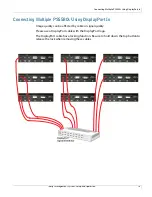
Page 18: ...14 Connecting Multiple PS5580s Using DisplayPort In Image quality can be affected by cable or signal quality Please use a DisplayPort cable with the DisplayPort logo The DisplayPort cable has a locki...

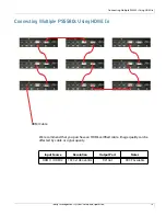
Page 19: ...Operation 15 Connecting Multiple PS5580s Using HDMI In We recommend that you purchase an HDMI certified cable Image quality can be affected by cable or signal quality HDMI Cable Input Source Resoluti...

Page 20: ...disys Management System Setup and Operation 16 Connecting Multiple PS5580s Using DVI In Image quality can be affected by cable or signal quality DVI Cable Input Source Resolution Output Port Notes DVI...

Page 21: ...Connecting Multiple PS5580s Using PC In Indisys Management System Setup and Operation 17 Connecting Multiple PS5580s Using PC In Image quality can be affected by cable or signal quality...

Page 22: ...m for RS232 with daisy chain connection is 30 sets If you need additional connection use an RS232 distributor The IR command for power on off is looped through all the displays All other commands from...

Page 23: ...ement System Setup and Operation 19 Connecting Ethernet Cable The control PC should be connected to one of the PS5580s with Ethernet cable For connection between PS5580s use RS232 cables LAN Cable dir...

Page 24: ...Direction buttons and OK button select the highlighted item or move from one menu to another horizontally buttons move the highlighted area up or down to select adjustment items within the menu 3 EXIT...

Page 25: ...ve the Main MENU Press MENU button to move the Main MENU Picture Adjustments Menu Item Adjusts this BRIGHTNESS Overall image and background brightness BACKLIGHT Backlight intensity CONTRAST Image brig...

Page 26: ...ue Each of the values can be adjusted by pressing 4 Exit from the MENU Press EXIT button to get out of the MENU 5 Move the Main MENU Press MENU button to move the Main MENU Screen A Mode Adjustments M...

Page 27: ...this AUTO SETUP Screen size H V positions Clock Clock Phase all adjusted AUTO ADJUST for PC In Select YES or NO for AUTO ADJUST Screen Size H position V position Clock Clock Phase will be adjusted POW...

Page 28: ...r LAN OFF LAN SETTING Configure the IP address of the set for control via Ethernet OSD TURN OFF H POSITION V POSITION ROTATION of OSD INFO DISPLAY TRANSPARENCY Configures the OSD menu display Turns of...

Page 29: ...999 TILING MENU LOCK Locks the tiling menu to protect the tiling display setting GROUP ID Setup the Tiling Group A through J IR control Prevents the display from being controlled by the remote control...

Page 30: ...to display the menu on the screen b Select PICTURE and press OK c Select BACKLIGHT and press OK Adjust Backlight to 80 d Select COLOR BALANCE and set all three GAINS to 50 all three RGB GAINS to 100...

Page 31: ...800 x 600 30 998 50 30 75 37 879 60 40 XGA 1024 x 768 48 363 60 65 1280 x 768 47 776 60 79 5 1280 x 960 60 60 108 SXGA 1280 x 1024 52 679 50 88 5 63 981 60 108 1360 x 768 39 564 50 69 1360 x 768 47 71...

Page 32: ...disys Management System Setup and Operation 28 1080i50 28 125 50 74 250 1080i60 33 750 60 74 250 1080p50 56 250 50 148 5 1080p60 67 5 60 148 5 Timing fH kHz fV Hz Dot Clock MHz HDMI VGA DVI DisplayPor...

Page 33: ...and by 1 0W Surface Treatment Haze 0 Hard coating 2H Viewing Angle H 178 V 178 Response Time G to G 8msec typical Environmental Condition Temperature 5 35 C Humidity 35 75 Input Signal Supported Resol...

Page 34: ...Dimensions Indisys Management System Setup and Operation 30 Dimensions 61 3...

Page 35: ...is Directive is maintained at the corporate headquarters of Planar Systems Inc 1195 NW Compton Drive Beaverton OR 97006 Note This equipment has been tested and found to comply with the limits for a Cl...

Page 36: ...ined Planar employees When you purchase a Planar product you get more than a display you get the service and support you need to maximize your investment To find the latest warranty and service inform...

Page 37: ...ours of operation 32 phone numbers 32 website 32 D dimensions 30 document number ii E environmental conditions 4 H handling the display 7 hours of operation for customer support 32 I information regul...

Page 38: ...setup B menu 24 specifications 29 supported resolutions 27 T telephone numbers for customer support 32 temperature requirements for normal use 6 temporary image retention avoiding 6 definition 6 ther...

Reviews: