background image

3

En

Before Proceeding

English

Before Proceeding

How to Use This Manual

This manual is set up to follow the course of actions and
operations in the order that would seem most logical for
someone setting up this unit.

Once the unit has been taken out of the box and it has
been confirmed that all the parts have been received, it
may be beneficial to look over the section “Part Names
and Functions” starting on page 6 to become acquainted
with the plasma monitor and remote control unit, as their
respective buttons and controls will be referred to
throughout this manual.

The section “Installation and Connections” starting on
page 10 covers all the necessary points regarding
installation of the plasma display and connections to a
wide variety of components.

The section “Setting Up the System” starting on page 17
covers the necessary on-screen menu settings to
establish correct linkage between the plasma display and
connected components. Depending on the connections
made, this section may or may not be necessary.

The remainder of the sections in this manual is dedicated
to the basic operations associated with selecting a source
component up to the more complex operations
associated with adjusting the plasma display picture to
match the requirements of specific components and
personal preferences.

Screen Displays

The example screen displays provided in this manual are
those for the PDP-50

P

 model. The PDP-43

P display 

differs as shown:

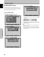
Example of PDP-50

P

 Screen Display:

÷

 The PDP-50

P

 screen display has a non-

displaying border at each side of the display.

MAIN  MENU

INPUT1

SELECT

ENTER

EXIT

SET

MENU

PICTURE

SCREEN

SET UP

OPTION

:

0

:

6

+
+
+

0

:

6 0

:

6 0

:

0

:

0

C O N T R A S T

:

0

B R
R L E V E L

I GH T .

.

G L E V E L

.

B L E V E L

.

H E NH AN CE

.

V E NH AN CE

.

R S E T

E

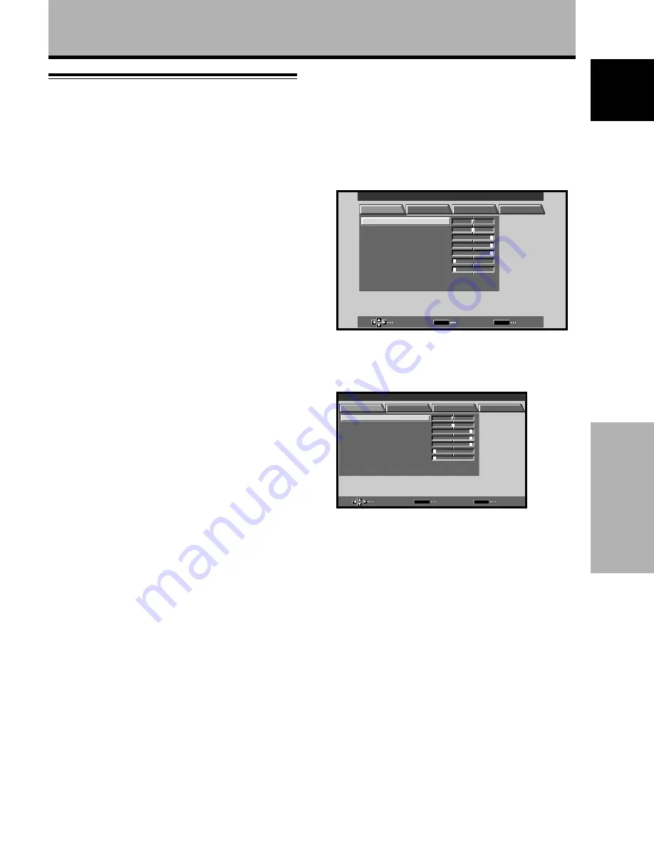
Example of PDP-43

P

 Screen Display:

÷

 The PDP-43

P

 screen display fills the display area in

both horizontal directions.

M A I N     M E N U

I N P U T 1

SELECT

ENTER

EXIT

SET

MENU

PICTURE

SCREEN

SET UP

OPTION

:

0

:

6

+
+
+

0

:

6 0

:

6 0

:

0

:

0

C O N T R A S T

:

0

B R
R

L E V E L

I GH T .

.

G

L E V E L

.

B

L E V E L

.

H

E N H A N C E

.

V

E N H A N C E

.

R

S E T

E

Please note that the actual contents displayed are the
same for both the PDP-50

P

 and PDP-43

P

.

Summary of Contents for PDP43P

Page 1: ...PDP 50P AND PDP 43P OPERATING INSTRUCTIONS ...

Page 2: ...video card is required if you wish to view other video signals on the monitor For details consult your local retail dealer Contents related to system specifications power requirements accessories and other information differ with respect to the country where this unit is purchased ...

Page 3: ...u will find it useful in the future Notes on Installation Work This product is marketed assuming that it is installed by qualified personnel with enough skill and competence Always have an installation specialist or your dealer install and set up the product Planar cannot assume liabilities for damage caused by mistake in installation or mounting misuse modification or a natural disaster Note for ...

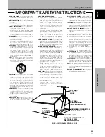
Page 4: ...s are found on labels attached to the product They alert the operators and service personnel of this equipment to any potentially dangerous conditions WARNING This symbol refers to a hazard or unsafe practice which can result in personal injury or property damage CAUTION This symbol refers to a hazard or unsafe practice which can result in severe personal injury or death i CAUTION WHEN POSITIONING...

Page 5: ...on an unstable cart stand tripod bracket or table The product may fall causing serious injury to a child or adult and serious damage to the product Use only with a cart stand tripod bracket or table recommended by the manufacturer or sold with the product Any mounting of the product should follow the manufacturer s instructions and should use a mounting accessory recommended by the manufacturer CA...

Page 6: ... Setting Up the System 17 Setup after Connection 17 Operations 19 Selecting an Input Source 19 Screen Size Selection 21 Partial Image Enlargement POINT ZOOM 23 Automatic Power OFF 24 Display Panel Adjustments 25 Adjusting the Picture Quality 25 Adjusting the Image Position and Clock Automatic Adjustment 26 Manual Adjustment of Screen Position and Clock 27 Other Operations 28 Rewriting the Input Di...

Page 7: ...er Control function is selected power consumption is reduced by 20 compared to the normal operating mode MODE 1 with color bar signal input Features PDP 50P PDP 43P Introduces newly developed 43 Wide Plasma Panel The new wide high precision 43 plasma panel 1024x768 16 9 pushes the envelope of previous high luminance panels producing brighter clearer images with higher contrast Newly developed full...

Page 8: ...ctions made this section may or may not be necessary The remainder of the sections in this manual is dedicated to the basic operations associated with selecting a source component up to the more complex operations associated with adjusting the plasma display picture to match the requirements of specific components and personal preferences Screen Displays The example screen displays provided in thi...

Page 9: ... shown at each step are provided as a visual guide to confirm that the procedure is proceeding as it should Please familiarize yourself with this process before continuing on with the rest of this manual 1 Press MENU to display the menu screen MAIN MENU INPUT1 SELECT ENTER EXIT SET MENU PICTURE SCREEN SET UP OPTION 0 6 0 6 0 6 0 0 0 CONT RAST 0 BR R L EV EL I GHT G L EV EL B L EV EL H E NHANCE V E...

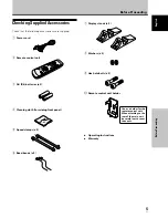
Page 10: ...A R6 batteries x 2 4 Cleaning cloth for wiping front panel 5 Speed clamps x 2 6 Bead bands x 2 Before Proceeding 7 Display stands x 2 8 Washers x 2 9 Hex hole bolts x 2 0 Remote control unit holder Operating Instructions Warranty Use as a holder for the remote control unit When attaching to the rear of the main unit be careful not to cover the vents ...

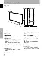
Page 11: ... mode page 19 5 INPUT button Press to select input page 19 6 MENU button Press to open and close the on screen menu pages 17 to 30 7 ADJUST 5 3 2 buttons Use to navigate menu screens and to adjust various settings on the unit Usage of cursor buttons within operations is clearly indicated in the on screen display pages 17 to 30 8 SET button Press to adjust or enter various settings on the unit page...

Page 12: ...e the remote control Do not use the remote control unit in a location subject to direct sunlight heat radiation from a heater or in a place subject to excessive humidity When the remote control unit s batteries begin to wear out the operable distance will gradually become shorter When this occurs replace all batteries with new ones as soon as possible Inserting the batteries in the remote control ...

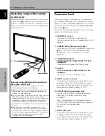
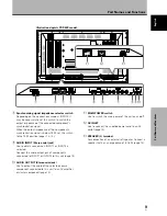
Page 13: ...e main power of this unit is off or in standby mode page 13 7 INPUT2 BNC jacks For connection of a personal computer PC or similar component Make sure that the connection made corresponds to the format of the signal output from the connected component pages 12 to 14 If you are having difficulty with operation of the remote control unit The remote control unit may not operate if there are objects p...

Page 14: ...onents connected to INPUT1 or INPUT2 to this unit page 14 0 AUDIO OUTPUT Stereo mini jack Use to output the audio of the selected source component connected to this unit to an AV amplifier or similar component page 14 1 2 3 4 5 6 7 89 0 L IN OUT CONTROL COMBINATION IN OUT RS 232C ANALOG RGB ANALOG RGB INPUT1 OUTPUT G B R HD VD ON SYNC H V SYNC Ô 75 2 2 Ω kΩ INPUT INPUT1 2 OUTPUT AC INLET SPEAKER 8...

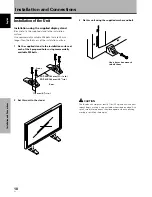
Page 15: ...d stand to the installation surface at each of the 4 prepared holes using commercially available M8 bolts 2 Set this unit in the stand Front Rear 110 mm 4 5 16 in Use a 6 mm hex wrench to bolt them CAUTION This display unit weighs at least 67 lbs 30 kg and has little front to back depth making it very unstable when stood on edge As a result two or more persons should cooperate when unpacking movin...

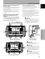
Page 16: ...be inserted 1 2 inch 12 mm to 11 16 inch 18 mm into the main unit from the attaching surface for both a holes and b holes Refer to the side view diagram below As this unit is constructed with glass be sure to install it on a flat unwarped surface Installation and Connections Center line b hole b hole Rear view diagram PDP 43P b hole Center line b hole a hole a hole Air vents fan CAUTION To avoid m...

Page 17: ...jack Connection to a personal computer Connection method differs depending on the computer type When connecting please thoroughly read the computer s instruction manual Before making connections be sure to make sure that the personal computer s power and this unit s main power is off For the PC input signals and screen sizes that this unit is compatible with please refer to supplement 1 pages 35 a...

Page 18: ...LOG RGB INPUT1 OUTPUT With this unit it is possible to output the video signal to an external monitor or other component from the OUTPUT INPUT1 terminal Note A video signal will not be output from the OUTPUT INPUT1 terminal when the main power of this unit is off or in standby To an external monitor Connection of G ON SYNC analog RGB source Make G ON SYNC connections for a personal computer with o...

Page 19: ...omponent s power and the unit s main power is off Connecting the speakers This unit is equipped with speaker output jacks for connection to the speaker system not supplied specially designed for use with this unit Refer to the illustrations below when making connections to the speaker terminals on this unit 10 mm Note When making speaker connections be sure to match the polarities and of the speak...

Page 20: ... converter plug use an outlet with a ground terminal and screw down the ground line Control Cord Connection When control cord connections are made remote control operation of connected Planar components that bear the Î logo mark is done through the remote sensor on this unit When the connection is made to the CONTROL IN jack on another unit the remote sensor of that component will no longer receiv...

Page 21: ...re designed to be difficult to undo once in place Please attach carefully To attach the speed clamps to the main unit Connect the speed clamps using the 4 holes marked with below depending on the situation To remove speed clamps Using pliers twist the clamp 90 and pull it outward In some cases the clamp may have deteriorated over time and may be damaged when removed As viewed from the rear of the ...

Page 22: ...N SYNC or Composite SYNC signal for WIDE VGA or WIDE XGA inputs set the screen display mode manually 8 When the setup is completed press MENU to exit the menu screen Note Make this setup for each input INPUT1 and INPUT2 Setup after Connection After components have been connected to INPUT1 or INPUT2 on screen setup is necessary Follow the procedure described below and make settings as they apply to...

Page 23: ... A I NP UT I NP UT 1 L E B L A MAIN MENU INPUT1 3 Press 5 to select CLAMP POSITION SELECT CHANGE EXIT SET MENU PICTURE SCREEN SET UP OPTION NT S E T T I N CL AMP POWE R G OF F P S I T I ON O M NAGEME A I NP UT I NP UT 1 L E B L A V GA A U TO MAIN MENU INPUT1 4 Press SET to select LOCKED SELECT CHANGE EXIT SET MENU PICTURE SCREEN SET UP OPTION NT S E T T I N CL AMP POWE R G OF F P S I T I ON O M NA...

Page 24: ...gnal input will cause the menu screen to turn off If the input computer signal is not supported by the display the following message will be displayed 0 8 5 5 1 2 6 8 4 k H z f V 1 7 1 7 H z f H P O U SUP N S R ED T I NAL G CAU I O N T FUL L I NPUT 1 X 0 2 0 k H z f V 7 7 1 5 H z f H T OU N O A R F G E CAU I O N T FUL L I NPUT 1 4 Use VOLUME on the remote control unit to adjust the volume If no au...

Page 25: ...tomatically canceled about 8 minutes after the button is pressed and the volume level is adjusted to the minimum level Press VOLUME or VOLUME to adjust the volume at a desired level To confirm display settings DISPLAY Press DISPLAY on the remote control unit The currently selected input screen size and refresh rates will be displayed for about 3 seconds O D BY T DOT I NPUT 1 0 6 0 4 6 0 8 4 0 k H ...

Page 26: ... a wide screen a portion of the picture may be cut off or appear deformed Be aware that when the display is used for commercial or public viewing purposes selecting the PARTIAL or FULL mode settings may violate the rights of authors protected under copyright law When DOT BY DOT or 4 3 screen sizes are selected the display position is moved slightly each time the power is turned on in order to prev...

Page 27: ... source However in order to maintain the 1 1 ratio a portion of the display will not appear on the screen Use 5 to adjust the position of the video image on the screen 768 lines 1024 lines Moving the screen position upward or downward Supported only on PDP 50P During personal computer input 1280 x 1024 60Hz only even when the PARTIAL setting is selected the position of the screen can be adjusted b...

Page 28: ... used to move the enlarged portion up down and right left If no operation is undertaken for three seconds or more the display screen will disappear SET or 5 2 3 can be pressed again if desired to change the zoom ratio or display position 4 Press the remote control unit s POINT ZOOM once again to cancel the point zoom operation The point zoom function will also be canceled whenever the input signal...

Page 29: ...AU T O S E T T I N CL AMP POWE R G OF F P S I T I ON O M NA GEME A I NP UT I NP UT 1 L E B L A V GA NT MAIN MENU INPUT1 When using INPUT 2 PICTURE SCREEN SET UP OPTION V GA AU T O S E T T I N CL AMP A UTO POWE R G OF F OF F P S I T I ON O I NP UT I NP UT 2 L E B L A MAIN MENU INPUT2 4 Press SET to confirm selection of the POWER MANAGEMENT or AUTO POWER OFF When OFF is selected the display will con...

Page 30: ...s PICTURE mode adjustment items Below are brief descriptions of the options that can be set in the PICTURE mode CONTRAST Adjust according to the surrounding brightness so that the picture can be seen clearly BRIGHT Adjust so that the dark parts of the picture can be seen clearly R LEVEL Adjust the amount of red in the picture G LEVEL Adjust the amount of green in the picture B LEVEL Adjust the amo...

Page 31: ...ote Perform this adjustment individually for each input function INPUT 1 INPUT 2 and each signal type Press AUTO SET UP on either the main unit or remote control unit Optimum settings may not be possible for low luminance and certain other kinds of signals In this case follow the instructions in the section Manual Adjustment of Screen Position and Clock to make more precise adjustments AUTO SET UP...

Page 32: ...ow are brief descriptions of the options that can be set in the SCREEN mode POSITION H POSITION Adjust the picture s position to the left or right V POSITION Adjust the picture s position upward or downward CLOCK PHASE CLOCK Adjust letter breakup or noise on the screen This setting adjusts the unit s internal clock signal frequency that corresponds to the input video signal PHASE Adjust so that th...

Page 33: ...E B L A T E S RE D N E A E C A S P MAIN MENU INPUT1 5 Press 2 3 5 to select the first desired character here C then press SET to confirm repeat this step to input up to eight desired characters SELECT SET EXIT SET MENU BACK SPACE J M K L B C D E F G H W Z X Y N O P Q R S T V U 9 0 1 2 3 4 5 6 8 7 I NP UT I NP UT 1 L E B L A T E S RE E C A S P D N E A C I MAIN MENU INPUT1 Usable characters include ...

Page 34: ...RD setting but at a even lower levels of power consumption MODE 2 fixes the screen brightness regardless of the input signal This is effective for reducing panel deterioration due to screen burning 4 Following completion of settings press MENU to return to normal screen display Note The POWER CONTROL setting affects all input sources AUTO FUNCTION This display is equipped with an optional AUTO FUN...

Page 35: ...O OUT The signal level produced at the AUDIO OUT jack can be set to FIXED or VARIABLE linked to the VOLUME as desired 1 Press MENU The onscreen menu will be displayed MAIN MENU INPUT1 SELECT ENTER EXIT SET MENU PICTURE SCREEN SET UP OPTION 0 6 0 6 0 6 0 0 0 CONT RAST 0 BR R L EV EL I GHT G L EV EL B L EV EL H E NHANCE V E NHANCE R S ET E 2 Press 2 3 to select OPTION SELECT CHANGE EXIT SET MENU PIC...

Page 36: ...shooting What may at first seem to be an malfunction may be remedied with a quick check Please check to see if a warning is displayed on the screen If displayed refer to the table below and check the mode If there is no display check to see if the problem is listed on page 32 The problem may also be caused by something other than this unit so please also check the other components being used such ...

Page 37: ...n is displayed in a small size Letter breakup on screen A sharp sound is sometimes heard from the cabinet Bright portions of image appear to be losing intensity Speckles or noise appears on screen Stripes appear on the screen Operation is not possible Sound is heard from inside the unit Fan isn t moving Fan speed changes Check the input signal compatibility chart pages 35 and 36 Is the correct scr...

Page 38: ...DBY ON is pressed to set the unit to the standby mode the indicator will flash red for several seconds page 19 Other than this if the power turns off by itself or refuses to turn on or if the red indicator conditions flashing a malfunction may be indicated Immediately disconnect the power plug and consult your dealer or a service center Additional Information About the plasma panel s protection fu...

Page 39: ...Input Mini D sub 15 pin socket connector RGB signal G ON SYNC compatible RGB 0 7 Vp p 75 Ω no sync HD CS VD TTL level positive and negative polarity 2 2 kΩ G ON SYNC 1 Vp p 75 Ω negative sync Compatible with Microsoft s Plug Play VESA DDC1 2B Output Mini D sub 15 pin socket connector 75 Ω with buffer Additional Information INPUT 2 Input BNC jack x5 RGB signal G ON SYNC compatible RGB 0 7 Vp p 75 Ω...

Page 40: ...46 9kHz 53 7kHz 49 7kHz 31 7kHz 48 4kHz 56 5kHz 60 0kHz 60 2kHz 68 7kHz 53 7kHz 64 9kHz 67 7kHz 68 7kHz 61 8kHz 71 7kHz 45 1kHz 48 4kHz 56 1kHz 60 0kHz 64 0kHz 80 0kHz 91 1kHz 75 0kHz 81 3kHz 87 5kHz 93 8kHz 106 3kHz 1024x768 1024x768 1024x768 1024x768 1016x768 984x768 1024x768 960x768 1024x768 640x480 800x600 832x624 852x480 1024x768 1280x768 4 3 NEC PC 9800 NEC PC 9800 852x480 864x480 Apple Maci...

Page 41: ...Hz 68 7kHz 61 8kHz 71 7kHz 45 1kHz 48 4kHz 56 1kHz 60 0kHz 64 0kHz 80 0kHz 91 1kHz 75 0kHz 81 3kHz 87 5kHz 93 8kHz 106 3kHz 768x768 768x768 768x768 768x768 768x768 768x768 738x768 768x768 720x768 768x768 640x480 800x600 832x624 852x480 1024x768 4 3 NEC PC 9800 NEC PC 9800 852x480 864x480 Apple Macintosh 13 1072x600 Apple Macintosh 16 1376x768 indicates Apple Macintosh 19 Apple Macintosh 21 Sun Mic...

Page 42: ...68 line resolution Supplement 2 Signal assignment of INPUT 1 Mini D sub 15 pin socket connector Input Output 1 2 3 4 5 6 7 8 9 10 11 12 13 14 15 R or CR PR G or Y B or CB PB NC No connection GND GND GND GND DDC 5V GND NC No connection DDC SDA HD or H V SYNC VD DDC SCL NC No connection NC No connection NC No connection 5 1 15 11 6 10 Pin No Apple and Macintosh are registered trademarks of Apple Com...

Page 43: ...tems Inc 09 02 Planar is a registered trademark of Planar Systems Inc Other brands and names are the property of their respective owners Technical information in this document is subject to change without notice 020 0256 00 ...

Reviews: