background image

Title:  Product Specification: LC12 High-Bright Monitor 

Page 2 of 24 

Document Number: 023-0284-01 


          Revision:  A 

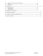
Table of Contents 


1.0


INTRODUCTION .......................................................................................................................................................................................4


1.1 

Display Format.................................................................................................................... 4 

2.0


BASIC CONSTRUCTION........................................................................................................................................................................5


2.1


Weight

................................................................................................................................. 5 

2.2 

Mechanical Mounting Requirements.................................................................................. 5 

2.3 

Monitor Electronics............................................................................................................. 5 

2.4 

Cooling Fan......................................................................................................................... 5 

2.5 

Vandal Glass ....................................................................................................................... 5 

2.6 

Air Filtration ....................................................................................................................... 5 

2.7 

Connectors .......................................................................................................................... 5 

2.8 

LCD Controller Board ........................................................................................................ 6 

2.9 

Grounding ........................................................................................................................... 6 

2.10 

External And Internal Controls ........................................................................................... 6 

3.0


ENVIRONMENTAL ..................................................................................................................................................................................7


3.1 

Temperature and Humidity................................................................................................. 7 

3.2 

Solar Loading...................................................................................................................... 7 

3.3 

Altitude................................................................................................................................ 8 

3.4 

Mechanical Vibration and Shock ........................................................................................ 8 

4.0


VIDEO SIGNAL INPUT REQUIREMENTS .....................................................................................................................................9


4.1 

Video Input Lines................................................................................................................ 9 

4.2 

Signal Functions .................................................................................................................. 9 

4.3 

Signal Quality ................................................................................................................... 12 

4.4 

Timing and Frequency...................................................................................................... 12 

4.5 

Video Signal On-Off Sequences....................................................................................... 13 

5.0


DC POWER INPUT REQUIREMENTS ........................................................................................................................................... 15


5.1 

DC Power Input Lines ...................................................................................................... 15 

5.2 

DC Input  Voltage / Current .............................................................................................. 15 

5.3 

Power On-Off Sequences.................................................................................................. 16 

6.0


DISPLAY PERFORMANCE ................................................................................................................................................................ 16


6.1 

Display Luminance ........................................................................................................... 16 

6.2 

Display Contrast................................................................................................................ 16 

6.3 

Display Uniformity ........................................................................................................... 17 

6.4 

Display Chromaticity........................................................................................................ 17 

6.5 

LCD Panel - Physical Image Characteristics .................................................................... 17 

7.0


DISPLAY COSMETICS ........................................................................................................................................................................ 18


8.0


REGULATORY AGENCY REQUIREMENTS .............................................................................................................................. 19


8.1 

Safety Certification........................................................................................................... 19 

8.2 

CE Marking (Declaration according to ISO/IEC Guide 22 and EN45014)...................... 19 

8.3 

RFI Emission Certification ............................................................................................... 20 

Summary of Contents for LC12

Page 1: ...Title Product Specification LC12 High Bright AMLCD Monitor Page 1 of 24 Document Number 023 0284 01 Revision A Product Specification LC12 High Bright Monitor Document Number 023 0284 01 Revision A ...

Page 2: ... 3 4 Mechanical Vibration and Shock 8 4 0 VIDEO SIGNAL INPUT REQUIREMENTS 9 4 1 Video Input Lines 9 4 2 Signal Functions 9 4 3 Signal Quality 12 4 4 Timing and Frequency 12 4 5 Video Signal On Off Sequences 13 5 0 DC POWER INPUT REQUIREMENTS 15 5 1 DC Power Input Lines 15 5 2 DC Input Voltage Current 15 5 3 Power On Off Sequences 16 6 0 DISPLAY PERFORMANCE 16 6 1 Display Luminance 16 6 2 Display C...

Page 3: ...8 4 System Transient Disturbance Requirements 20 8 5 Labeling 20 8 6 Color Coding 20 9 0 RELIABILITY 20 9 1 Design Workload 20 9 2 Critical Failures 21 9 3 Failure Definition 21 10 0 DESCRIPTION OF WARRANTY 21 11 0 SUPPORT AND SERVICE 22 12 0 GLOSSARY OF TERMS AND ABBREVIATIONS 22 13 0 REVISION HISTORY 24 ...

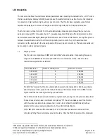
Page 4: ... with IBM VGA1 and VESA2 video standards Its operating frequency range is 31 5 KHz 56 5 KHz horizontal 60 Hz 72 Hz non interlaced vertical Specific video resolutions supported are as follows For IBM VGA1 modes the Monitor will accept 640 pixels horizontally 400 or 480 lines vertically and 800 pixels or 1024 pixels horizontally 600 lines or 768 lines vertically for the VESA2 modes Figure 9 defines ...

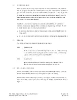
Page 5: ... designed to operate with a vandal glass 289 mm x212 mm x 10 mm in place This vandal glass in not provided with the Monitor 2 6 Air Filtration An air filter mesh is included to prevent ingress of insects and ensure continual flow of cooling air within the Monitor The air filter mesh is externally accessible for cleaning 2 7 Connectors There are two 2 connectors supplied as an integral part of the ...

Page 6: ...ixel scaleable filters providing text sharpening and graphics smoothing for improved image quality Color depth enhancement by performing spatial temporal dithering reducing visual artifacts 2 9 Grounding Two 2 types of ground are provided Chassis and Signal ground 2 9 1 Chassis Ground The chassis ground is a conductor that is grounded to the earth within user circuitry It is not used for current c...

Page 7: ...lor changes are allowed depending on ambient temperature This phenomenon is reversible Note 4 Tair 30 C 15 RH exterior face of Vandal Shield Tair 54 C 100 RH exterior face of Vandal Shield Note 5 Upper operating temperature limit of 60 C is without solar loading See section 3 2 for operating temperature conditions with solar load Reference to room ambient is interpreted as 20 C 25 C 68 F 77 F and ...

Page 8: ...ar approved rigid retaining fixture 3 4 1 Vibration Non Operating sinusoidal 10 200 Hz 0 9g acceleration 120 seconds per sweep for 15 minutes three axes x y z Following exposure unit shall meet all performance requirements Non operating random 10 200 Hz 0 02g2 Hz 10 min axis three x y z Following exposure unit shall meet all performance requirements 3 4 2 Shock Non operating 30 g 2 5 ms duration s...

Page 9: ...d Reference 11 Monitor Sense Line 1 connected to Pin 10 12 Monitor Sense Line 2 NC 13 Horizontal Sync Input 14 Vertical Sync Input 15 NC Table 2 Video Signal Connector Pin Number Assignments The Video Signal Connector that connects to the customer s equipment is a female 15 pin connector in a high density 9 pin D Shell housing Pin number assignments are defined in Table 2 and physical layout as se...

Page 10: ...with the video analog input This is necessary to provide a uniform user color change on the screen in response to a uniformly stepped analog input The Monitor must be capable of resolving a minimum color range of 262 144 displayable colors 6 bit resolution for Red Green and Blue This interpolates to 64 shades of gray or color at the Red Green and Blue analog video inputs Accomplishing specified sh...

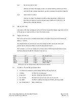
Page 11: ...ing Frequency Sync Polarity Horizonta l KHz Vertical Hz Horizonta l Vertical IBM VGA 640 x 400 31 468 70 IBM VGA 640 x 480 31 468 60 IBM VGA w Border 656 x 496 31 468 60 IBM VGA 720 x 400 31 468 70 IBM VGA w Border 738 x 414 31 468 70 VESA 800 x 600 48 077 72 VESA 1024 x 768 56 48 70 Table 3 Video Mode Definitions 4 2 2 2 Color Display Detection The video signal source determines which type of dis...

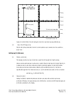
Page 12: ...Horizontal Sync Less than 50 ns Vertical Sync Less than 100 ns 4 4 Timing and Frequency 4 4 1 Video Horizontal And Vertical Sync Figure 6 illustrate video timing relationships the Monitor operates within when the specified video mode per Table 3 is applied Front Porch defines the time from end of active video data to the start of Horiz Vert Sync Pulse Back Porch defines the time from end of Horiz ...

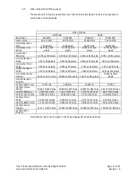
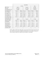
Page 13: ...636 us 16 pixels 1 120 us 56 pixels 0 320 us 24 pixels Horizontal Back Porch 1 907 us 48 pixels 1 907 us 48 pixels 1 280 us 64 pixels 1 920 us 144 pixels Horizontal Active Display 25 422 us 640 pixels 25 422 us 640 pixels 16 000 us 800 pixels 13 653 us 1024 pixels Horizontal Sync Polarity Vertical Scan Freq 70 087 Hz 59 94 Hz 72 184 Hz 70 069 Vertical Frame Period 14 268 ms 449 lines 16 683ms 525 ...

Page 14: ...splay 25 422 µs 640 dots 25 422 µs 640 dots 16 000 µs 800 dots Horizontal Sync Polarity Vertical Scan Frequency 70 087 Hz 59 94 Hz 72 187 Hz Vertical Frame Period 14 268 ms 449 line 16 683 ms 525 line 13 853 ms 666 line Vertical Blanking 1 557 ms 49 line 1 430 ms 45 line 1 373 ms 66 line Vertical Sync Pulse 0 064 ms 2 line 0 064 ms 2 line 0 125 ms 6 line Vertical Front Porch 0 381 ms 12 line 0 318...

Page 15: ...N LOK type with male pin contacts AMP 1 480699 Pin number assignments are define d in Figure 11 shown below is the physical layout as seen by the interface cable from the DC power source Figure 8 DC Power Input Connector Illustration 5 2 DC Input Voltage Current DC Input Voltage 12 vdc nominal 0 4 vdc Over the specified input voltage range No loss of image synchronization occurs White display lumi...

Page 16: ... The display provides one level of luminance used for both daylight and night viewing Minimum white light luminance at the screen center of the Monitor face is 1500 cd m2 467 fL in a darkened room environment with ambient light conditions less than 10 LUX 1fC incident illumination and at room temperature Reference MIL L 85762A 3 10 2 2 3 Luminance specification applies to the initial luminance i e...

Page 17: ...coordinate determination is the CIE 1976 UCS Uniform Chromaticity Scale u v system Color determination is performed normal to the display in a dark room environment with ambient light conditions less than 10 LUX 1fC incident illumination The measured u v color coordinates at room temperature for White light and the Red Green and Blue primaries are listed for reference purposes only Color u v Perce...

Page 18: ...en Blue Max 10 Red Green Red Blue Green Blue Min 0 200 Min 0 200 Min 0 200 Dark Defects Pixels Black Screen Red Green Blue Max 10 Red Green Red Blue Green Blue Min 0 040 Min 0 040 Min 0 040 Adjacent Pixel Groups Qty Allowed Pairs Qty Allowed Triplets Bright Defects Pixels White Screen Red Red Green Green Blue Blue Max 2 All colors Red Red Red Blue Blue Blue Green Green Green Max 0 All colors Dark ...

Page 19: ...ndards UL 1950 CAN CSA C22 2 No 950 95 Safety of Information Technology including electrical business equipment UL 291Standard for Automated Teller Machine EN 60950 Safety of Information Technology including electrical business equipment 8 2 CE Marking Declaration according to ISO IEC Guide 22 and EN45014 The Monitor does not inhibit customer from conforming to the following EC Directives Council ...

Page 20: ...e Monitor performs normally when subjected to static electricity discharges from persons touching the external surfaces of the Monitor Performance is verified by testing according to EN 50082 1 Ref IEC 801 2 1984 at severity level 3 4 Kv contact discharge 8 Kv air discharge 8 4 2 Electromagnetic Energy Susceptibility Requirements The Monitor performs normally in an electromagnetic field with a str...

Page 21: ... Failures Malfunctions attributable to the following causes shall not be classified as failures Improper installation or maintenance Abuse or misuse Exposure to environments outside the specified design range Lack of prescribed preventative maintenance Failures caused by test equipment used to control cycle and check the operation of Display units on test 10 0 Description of Warranty Seller warran...

Page 22: ...l Authorization number please contact Planar Systems Inc with the model number s and original purchase order number s When returning goods for repair please include a brief description of the problem and mark the outside of the shipping container with the RMA number Planar Systems Inc Customer Service 24x7 Online Technical Support http www planar com support Americas Support 1195 NW Compton Drive ...

Page 23: ...osite display signal which lies between the leading edges of a horizontal blanking pulse and the corresponding sync pulse Gray Scale Variations in the luminance value of white light from black to white Shades of gray are defined as gray scale graduations that differ by the square root of 2 Illuminance The density of luminance flux impinging on a surface It is the quotient of the flux divided by th...

Page 24: ...f synchronous or synchronization Tristimulus Value See Chromaticity Value and Color Data VESA Video Electronics Standards Association VGA Video Graphics Adapter White The common usage word for high luminance achromatic colors XGA Extended Graphics Adapter 13 0 Revision History REV REF DATE PAGE DESCRIPTION OF CHANGE BY A 14 Jan 05 All First release S Vahlsing ...

Reviews: