background image

                                   LA1550TS User Manual                                                    


Connecting the Display 


To setup this display, please refer to the following figure and procedures. 

1.   Be sure all equipments are turned off. 

2.   Connect the Paint Booth Cable to the connector on the back cover of the monitor. 

3.   Connect the Extension Cable to the Paint Booth Cable and the other end to PC. 

4.   Connect D-SUB connector from the extension Cable to VGA output connector on 

PC. 

5.  Connect RJ-45 connector from extension cable to USB Transmitter device and 

connect USB Transmitter device to PC USB port. 

6.  Connect power connector to 110VAC power brick.. 

7.  Connect Power cord to power brick and the other end into AC socket. 


Notice!


To ensure the LCD display works well with your computer, please configure the display 

mode of your graphics card to make it less than or equal to 1024 x 768 resolution and 

make sure the timing of the display mode is compatible with the LCD display. 
We have listed the compatible “Video Modes” of your LCD display in the appendix 

(on page 18) for your reference. 


Attention


This equipment is suitable for use in Class I, Division 2, Group A, B, C, D, or Non-

Hazardous Locations Only. 


Summary of Contents for LA1550TS

Page 1: ...LA1550TS USER MANUAL www planar com...

Page 2: ...opying recording or otherwise without prior written permission Windows is registered trademark of Microsoft Inc Other brand or product names are trademarks of their respective holders Important Recycl...

Page 3: ...Monitor 9 Connect the Display 10 Warning Explosion Hazard 10 Special installation Instructions 11 IV User Controls 12 Front Panel Controls 12 How to use the OSD 13 On Screen Display Menus 14 V Append...

Page 4: ...OUS AVERTISSEMENT RISQUE D ECPLOSION AVANT DE DECONNECTER L EEQUIPEMENT COUPER LE COURANT OU S ASSURER QUE L EMPLACEMENT EST DESIGNE NON DANGEREUX WARNING SUBSTITUTION OF COMPONENTS MAY IMPAIR SUITABI...

Page 5: ...istened with mild detergent to clean the display housing Use only high quality and safety approved AC DC adapter Disconnect the power plug from AC outlet if the product is not going to be used for an...

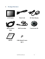
Page 6: ...LA1550TS User Manual 6 II Package Overview LCD Display Power Cord DC Power Supply Wall to monitor Cable USB Transmitter Touch Driver CD Manual VESA Mount Screws M4 8...

Page 7: ...LA1550TS User Manual 7 III Installation Product Overview Front View...

Page 8: ...ack of your monitor To mount the monitor on a swing arm or other mounting fixture follow the instructions included with the mounting fixture to be used Please note to mount your monitor to the devices...

Page 9: ...ansmitter device and connect USB Transmitter device to PC USB port 6 Connect power connector to 110VAC power brick 7 Connect Power cord to power brick and the other end into AC socket Notice To ensure...

Page 10: ...wer has been switched OFF or the area is known to be non hazardous Special installation Instructions Install system as per diagram above by qualified personnel in accordance with NFPA 70 NEC Article 5...

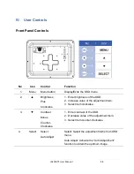
Page 11: ...ghtness of the OSD 2 Increase value of the adjustment item 3 Select item clockwise 3 Contrast Minus Counter Clockwise 1 Enter contrast of the OSD 2 Decrease value of the adjustment item 3 Select item...

Page 12: ...note the monitor has to be turned ON with a valid signal preset a Press and hold the Menu and Power key simultaneously for 1 second b The word OSD Lock Power Lock will appear for 2 seconds on the mon...

Page 13: ...y up and down 1 line increment Horizontal Size 0 100 The ratio of dividing frequency of the dot clock is adjusted Fine 0 100 The phase of the dot clock is adjusted OSD Left Right 0 100 Adjusts the OSD...

Page 14: ...lay Reconfigure the resolution of your computer to make it less than or equal to 1024 x 768 Problem Image has vertical flickering line bars Use Fine to make an adjustment Check and reconfigure the dis...

Page 15: ...splay has been powered on but it cannot receive any signal from the computer graphics card Check all the power switches power cables and VGA signal cable Going to Sleep The LCD is under the power savi...

Page 16: ...LA1550TS User Manual 16 Product Dimensions...

Page 17: ...MAC XGA 640 x 480 35 66 VESA VGA 640 x 480 37 86 72 VESA SVGA 640 x 480 37 5 75 VESA SVGA 800 x 600 35 16 56 VESA SVGA 800 x 600 37 88 60 VESA SVGA 800 x 600 46 88 75 VESA XGA 800 x 600 48 08 72 MAC X...

Page 18: ...Division 2 groups or unclassified locations Control drawing WARNING EXPOSURE TO SOME CHEMICALS MAY DEGRADE THE SEALING PROPERTIES OF MATERIALS USED IN THE DEVICES WARNING EXPLOSION HAZARD DO NOT DISCO...

Page 19: ...ide reasonable protection against harmful interference with the equipment is operated in a commercial environment This equipment generates uses and can radiate radio frequency energy and if not instal...

Page 20: ...m Online Technical Library http www planar com support Hours M F 3am 7pm ET 11am 3am GMT 2008 Planar Systems Inc Planar is a registered trademark of Planar System Inc Other brands and names are the pr...

Reviews: