background image


Preface 


P

REFACE


About this manual 

This manual is designed to assist you in setting up and using the LCD monitor. Information in this document has been 
carefully checked for accuracy; however, no guarantee is given to the correctness of the contents. The information in this 
document is subject to change without notice. This document contains proprietary information protected by copyright. All 
rights are reserved. No part of this manual may be reproduced by any mechanical, electronic or other means, in any form, 
without prior written permission of the manufacturer. 

Copyright 

 Copyright 2001, All Rights Reserved 

FCC Compliance Statement 

This device complies with part 15 of the FCC Rules. Opeartion is subject to the following two conditions: 

1.


this device may not cause harmful interference, and 

2.


this device must accept any interference received, including interference that may cause undesired operation. 

FCC WARNING 

This equipment has been tested and found to comply with the limits for a Class B digital device, pursuant to Part 15 of the 
FCC Rules. These limits are designed to provide reasonable protection against harmful interference in a residential 
installation. 

This equipment generates, uses and can radiate radio frequency energy and, if not installed and used in accordance with the 
instructions, may cause harmful inerference to radio communications. 

However, there is no guarantee that interference will not occur in a particular installation. If this equipment does cause 
harmful interference to radio or television reception, which can be determined by turning the equipment off and on, the user 
is encouraged to try to correct the interference by one or more of the following measures: 


Reorient or relocate the receiving antenna. 


Increase the separation between the equipment and the receiver. 


Connect the equipment into an outlet different from that to which the receiver is connected. 


Consult the dealer or an experienced radio/TV technician for help. 

Caution: 

To comply with the limits for an FCC Class B computing device, always use the shielded signal cord supplied with this unit. 

The Federal Communications Commission warns that changes or modifications of the unit not expressly approved by the 
party responsible for compliance could void the user’s authority to operate the equipment. 


CE mark for Class B ITE 

(Following European standard EN55022/1998; EN61000-3-2/1995; EN61000-3-3/1995, EN55024/1998, 

EN60950/1992+A1+A2+A3+A4+A11) 


Radio Frequency Interference Statement 

Warning: 

This is a Class B product. In a domestic environment, this product may cause radio interference in which case the user may 
be required to take adequate measures. 

Summary of Contents for FWT1744NU

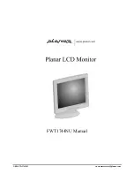
Page 1: ...1 866 PLANAR 1 customerservice planar com FWT1744NU Manual ...

Page 2: ......

Page 3: ...requency energy and if not installed and used in accordance with the instructions may cause harmful inerference to radio communications However there is no guarantee that interference will not occur in a particular installation If this equipment does cause harmful interference to radio or television reception which can be determined by turning the equipment off and on the user is encouraged to try...

Page 4: ...screen with a slightly dampened rag 2 Do not place your LCD monitor near a window Exposing the monitor to rain water moisture or sunlight can severely damage it 3 Do not place anything on top of the monitor to PC signal cord Make sure the cord is placed in an area where it will not be stepped on 4 Do not apply pressure to the LCD screen Excessive pressure may cause permanent damage to the display ...

Page 5: ... Connecting AC Power 3 Connecting Video 4 Connecting the Stereo Speakers 4 Power Management System 5 CHAPTER 2 6 The Display Controls 6 LCD Monitor Control Panel 6 Adjusting the Display 6 OSD Main Menu 7 APPENDIX A 10 Technical Information 10 TFT LCD Monitor Specifications 10 APPENDIX B 11 Supported Timing 11 APPENDIX C 12 Troubleshooting 12 Troubleshooting Procedures 12 ...

Page 6: ......

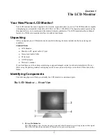
Page 7: ...uded in the box and in good condition Standard Items LCD Monitor Monitor to PC signal cable 15 pin Stereo Jack Audio Cable Power cord AC DC adapter This user s manual If you find that any of these items are missing or appear damaged contact your dealer immediately Do not throw away the packing material or shipping carton in case you need to ship or store the LCD monitor in the future Identifying C...

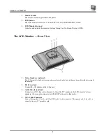
Page 8: ...e LCD monitor s built in stereo speakers are located in the bottom the monitor and face the direction of the desktop 2 DC Power Jack Connect the AC adapter cable to this jack 3 Audio Line in optional Connect your PC s line out to this jack to listen the PC s audio on the LCD monitor s stereo speakers You can also connect your CD ROM s line out to this jack 4 VGA Cable Connector Connect the supplie...

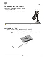
Page 9: ... its maximum extension can result in damage to the monitor Connecting AC Power Refer to the following instructions for connecting AC power to the LCD monitor 1 Plug the female end of the power cable into the AC adapter and the male end of the power cord into a wall socket The plug on the power cable will vary according to the electrical standard for your area 2 Plug the adapter power connector int...

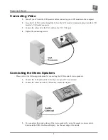
Page 10: ...e VGA cable to the PC s VGA port 4 Tighten the connecting screws Connecting the Stereo Speakers Please refer to the following instructions for connecting the LCD monitor s stereo speakers 1 Connect the 1 5M audio cable to the line out of your PC s sound card 2 Connect the other end to the LCD monitor s audio line in jack 3 You can adjust the sound volume of the stereo speakers by using the speaker...

Page 11: ...power management proposal The VESA DPMS proposal provides power saving modes by detecting the horizontal or vertical sync signal When the LCD monitor is in power saving mode or detects an incorrect timing the monitor screen will be blank and the power LED indicator starts blinking ...

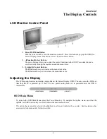
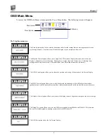
Page 12: ...ws you to increase the menu item value The button allows you to decrease the menu item value Adjusting the Display The LCD monitor features an intuitive menu driven On Screen Display OSD You can access the OSD any time that the PC is powered up If the PC is in a power saving mode or is powered down the OSD is inaccessible OSD Main Menu To activate the OSD Main Menu press the Power Menu key To navi...

Page 13: ...s should only be necessary if the results from Auto Adjust function are not satisfactory The OSD Control option allows you to adjust the position and setting of the monitor s On Screen Display The MISC Control option allows you to select the desired text language of the OSD adjust the monitor speaker volume and to display the current video information being sent to the monitor from your video card...

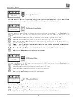
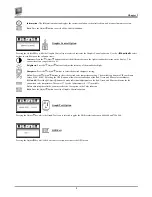
Page 14: ...k Press the Adjust buttons to stabilize the display clock timing An improper clock setting will result in wide vertical bands on the display Reset Press the Adjust button to reset the Monitor Control submenu values to the factory default values Exit Press the Adjust button key to exit the Monitor Control submenu OSD Control Option Pressing the Adjust key while the OSD Control icon is selected acti...

Page 15: ...djust buttons to select the desired sharpness setting Color Press the Adjust buttons to select the desired color temperature setting The available options are CIE coordinate values 9300 6500 Selecting the USER option allows for customization of the Red Green and Blue color coordinates R G and B Press the Adjust buttons to make individual adjustments to the Red Green and Blue coordinates for the cu...

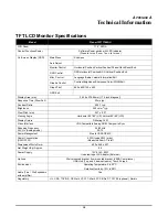
Page 16: ... Time Rise Fall 25ms typ Contrast Ratio 400 1 typ Brightness 220 cd m2 typ Pixel Pitch mm 0 27 x 0 27 Viewing Angle Horizontal 80 80 L R Vertical 80 80 U D Display Colors Dithering 16M Video Interface VGA Compatible Analog RGB Composite Sync Scanning Frequency H V Hz Analog mode 24 80kHz 50 75 Power Management Meets VESA DPMS Power Consumption ON OFF W 43W typical 5W max Measured from AC inlet Dim...

Page 17: ...5 00 37 50 A 11 VESA 800x600 36 00 56 25 35 16 A 12 SVGA 800x600 40 00 60 32 37 88 A 13 VESA 800x600 50 00 72 19 48 08 A 14 VESA 800x600 49 50 75 00 46 88 A 15 VGA 720x400 28 32 70 09 31 47 A 16 XGA 1024x768 65 00 60 00 48 36 A 17 VESA 1024x768 75 00 70 07 56 48 A 18 VESA 1024x768 78 75 75 03 60 02 A 19 1024x768 71 64 66 13 53 96 A 20 VESA 1152x864 108 00 75 00 67 50 A 21 1152x870 100 75 06 68 68 ...

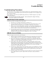
Page 18: ...ther Adjustment Control button until the lines disappear and you have a clear display PROBLEM There is no LCD Display If there is no display on the LCD refer to the following 1 Make sure that the power indicator on the LCD monitor is lit all connections are secure and the system is running on the correct timing Refer to the Addendum for information on timing 2 Turn off the LCD monitor and then tur...

Reviews: