background image

Page 4

For technical questions, please call 1-888-866-5797.

Item 69886 


Handle 

Grip (1)

Cotter Pin (3)

Handle (2)

Column (5)

Mounting 

Plate (8)

Wrapped Bushes (27)


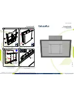
Figure D:  Attach Mounting Plate 

and Handle

5.  Grease Mounting Plate (8) shaft using 

chasis grease (sold separately).

6.  Insert Mounting Plate shaft into 

top of Column (5) while inserting 
shaft into wrapped bushes (27) on 
both ends. Insert the Handle (2) 
through the Mounting Plate (8) and 
secure with the Cotter Pin (3). Insert 
Handle Grip (1) onto Handle.

Mounting 

Plate (8)

Mounting 

Arm (9)

Bolt (10)

Washer (7)

Nut (6)

Pin (4)

Column (5)

Figure E:  Installing Arms 

and Locking Rotation

7.  Attach the Mounting Arms (9) to the 

slots in the Mounting Plate (8) using the 
Bolts (10), Washers (7), and Nuts (6).

8.  To lock Mounting Plate (8) rotation, 

align a hole on it with the hole on the top 
of the Column (5), and insert the Pin (4).

Summary of Contents for 69886

Page 1: ...ence 21d When unpacking make sure that the product is intact and undamaged If any parts are missing or broken please call 1 888 866 5797 as soon as possible Copyright 2021 by Harbor Freight Tools All...

Page 2: ...tions may result in personal injury and or property damage 1 Study understand and follow all instructions before operating this device 2 Do not exceed rated capacity Be aware of dynamic loading Sudden...

Page 3: ...the bottom of the Column 5 b Place Rear Beam 23 against the Column Align the holes in all three parts and secure with a Bolt 22 and Lock Washer 21 Middle Beam 20 Front Beam 11 Nut 14 Washer 13 Bolt 12...

Page 4: ...hile inserting shaft into wrapped bushes 27 on both ends Insert the Handle 2 through the Mounting Plate 8 and secure with the Cotter Pin 3 Insert Handle Grip 1 onto Handle Mounting Plate 8 Mounting Ar...

Page 5: ...he bolt heads must press against the back of the Arms if needed use flat washers not included as spacers 5 Tighten the Bolts 10 and Nuts 6 that hold the Mounting Arms 9 to the Mounting Plate 8 securel...

Page 6: ...s are found take it to a qualified technician for service or repair 1 BEFORE EACH USE inspect the general condition of the Stand Check it for cracks bends in the metal signs of unusual wear or any oth...

Page 7: ...Washer 8 8 17 Lock Washer 8 8 18 Nut M8 8 Part Description Qty 19 DVWHU 2 20 Middle Beam 1 21 Lock Washer 12 1 22 Bolt M12x80 1 23 Rear Beam 1 24 Wheel 2 25 Washer 14 2 26 Snap Ring 14 2 27 Wrapped B...

Page 8: ...llation normal wear and tear or to lack of maintenance We shall in no event be liable for death injuries to persons or property or for incidental contingent special or consequential damages arising fr...

Reviews: