background image


20

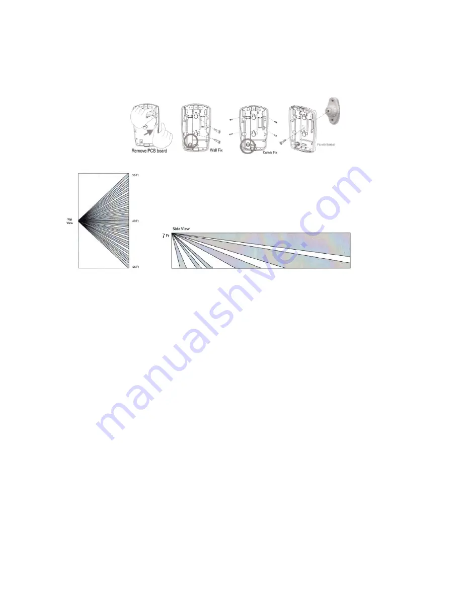
If you prefer to use screws to mount the motion sensor, follow the screw position 

shown in Figure E (optional) 


Detection Patterns 


Motion sensor Specifications 

Replacement Battery: CR123A 

The best Mounting Height: 

6.30 Feet 

Work temperature: less than 34 degree 

Range: Approximately 40 feet with 90 degree field of view (45 degrees 

to each side)


Summary of Contents for GSM-06

Page 1: ...PiSector All in ONE Wireless GSM Alarm System User Manual GSM 06 Read manual fully before use PiSector Inc USA www pisector com ...

Page 2: ...ZONE 21 3 8 SETTING DEFENSE ZONE PLACES 22 3 9 SETTING DEFENSE ZONE MODES 23 3 10 SETTING DEFENSE ZONE SIREN 24 3 11 ALARM DELAY SETTING 25 3 12 ADDING PHONE NUMBER 26 3 13 DELETING PHONE NUMBER 27 3 14 ADDING SMS CELL PHONE NUMBER 28 3 15 DELETING SMS CELL PHONE NUMBER 29 3 16 SET NET WORK CENTER FUNCTION 30 3 17 VOICE RECORDING 32 3 18 VOICE RECORDING REPLAY 33 3 19 SETTING SYSTEM DATE 34 3 20 S...

Page 3: ... 3 32 SIREN SETTING IN EMERGENCY MODE 49 3 33 ARM DISARM SMS NOTIFICATION 50 3 34 LANGUAGE SETTING 51 3 35 SET MAX RING TIMES BEFORE ANSWERING 52 3 36 CHOICE MODE OF ALARM NETWORK 53 3 37 FACTORY RESET 54 3 38 PASSWORD RESET 55 4 SYSTEM USAGE INSTRUCTIONS 56 4 1 OUT ARM 56 4 2 HOME ARM 57 4 3 DISARM 57 4 4 ANSWER ALARM CALL 58 4 5 REMOTE CONTROL 59 4 6 EMERGENCY ALARM CALL 60 4 7 USE AS TELEPHONE ...

Page 4: ...emote control by phone to arm disarm or intercom listen in One touch control ARM out arm STAY home arm via touch keypad or arm and disarm via remote controller or telephone 4 Arm Modes out arm home arm delay arm and timely arm for scheduling arm disarm times 8 Defense Zone Places SOS fire gas door hall window balcony and boundary 4 Arm Delay Modes Real time immediate 01 99 second delay 24 hours al...

Page 5: ...ted paper then close the cover Put small magnet next to sensor Install battery to IR motion sensor Install batteries and keep them switched off Know Your System 1 LCD Screen Resolution 128 64 English and Chinese display 2 LED Status Indicators POWER power and system activity indicator 1 2 3 ...

Page 6: ...sing Do not press the keypad heavily as this may reduce its sensitivity ARM press to enter OUT ARM status gives you 40 seconds to leave home before system is armed STAY press to enter HOME ARM status deactivates all sensors with Home defense zone mode and activates all other sensors CALL For making phone calls Enter the number you want to call and then press this CALL button Press again to end cal...

Page 7: ...A 4 B Connecting external keyboard B 5 GND Ground 6 Zone 1 Wired sensor 1 support both NO and NC 7 GND Ground 8 Zone 2 Wired sensor 2 support both NO and NC 9 GND Ground 10 Zone 3 Wired sensor 3 support both NO and NC 11 GND Ground 12 Zone 4 Wired sensor 4 support both NO and NC 13 GND Ground 14 G_ANT External antenna Ground 15 ANT External antenna 5 6 7 8 4 9 ...

Page 8: ...a external siren or wireless siren transmitter 8 Tel Your exist telephone device connector port LINE Main telephone line connector jack 9 SIM Card Slot Please pay attention to the direction arrow marked on the slot LOCK OPEN Do not insert or take out the SIM card when the main unit panel is powered on ...

Page 9: ...D does not light on you need to restart the main unit panel Please do it at least 10 seconds later as repeated power on and off in short times will shorten the service life of the system 4 The POWER indicator will flash once every 3 seconds after finding GSM network successfully This is the normal system state 5 Turn on the internal backup battery switch on the back of the main unit panel 6 Check ...

Page 10: ...eys 2 8 4 6 as direction keys up down left right At the disarm state input your 6 digit password default 888888 then press ENTER The main unit panel will sound a beep and the SET indicator lights on The screen will display Remote Control menu Fig 1 disarm status Fig 2 please enter password Fig 3 press ENTER to set ...

Page 11: ...the same as those already saved in the main unit panel Method enter remote controller setting menu press 4 or 6 to choose remote controller serial number press 8 to find Coding and then press ENTER to confirm Trigger the remote controller you want to add the main unit panel will make two beeps after receiving it And then press ENTER to confirm If the remote controller has been saved before after t...

Page 12: ...main unit has the same code with remote controller code Fig 2 choose remote control serial number and coding menu Fig 3 waiting to receive signal Fig 1 enter remote control menu Fig 4A recognize successfully Fig 5 press ENTER to save ...

Page 13: ...person can control the main unit panel Method enter remote controller setting menu press 4 or 6 to choose the remote controller you want to delete Press 8 to find Delete and then press ENTER Operation figures Fig 1 enter remote controller setting Fig 2 choose the controller you want to delete Fig 3 press ENTER to confirm ...

Page 14: ... of the saved sensors in the main unit panel has a unique address Method press key 888888 default password then press enter then press 6 to choose zone menu press enter you will see zone1 as Fig 2 if you press 6 will get zone2 zone3 you choice which zone you want to code the sensor then press 8 to find Coding then press ENTER to confirm you will see 000000000 as Fig 3 then trigger the sensor you w...

Page 15: ...s Fig 4B the main unit has the same code with sensor code Fig 1 enter defense zone setting Fig 2 choose zone number and press ENTER Fig 3 waiting signal from sensor Fig 4A recognize successfully Fig 5 press ENTER to save ...

Page 16: ...It will detect it and send the signal to control panel NOTE Please test each sensor before you mount the sensor to the appropriate location Place each sensor in the appropriate location Note If possible place the bracket on the stationary frame of door or window and place the magnet on the door or window itself Various orientations between the Bracket and Magnet may be used as long as 3 4 distance...

Page 17: ...R MAGNET TO ADJUST ALIGNMENT Once you have determined the appropriate location and orientation for the Bracket and Magnet attach them with double sided tape the Magnet Space and Bracket Space are optional only apply when your door window gap is big or very low ...

Page 18: ...s set to on but if you do not want a flashing light when the sensor detects an intruder you can turn it off When the battery is low the LED light becomes yellow Make sure S2 at the DF position for system GSM06 Note Please test each sensor before you mount the sensor in the appropriate location Test the Motion Sensor The Motion Sensor is in Walk Test mode during the first 3 minutes after the front ...

Page 19: ... not expired or B the Motion Sensor is not in communication with the PiSECTOR system main console If you want to re start the Walk Test mode again open the Front Cover as shown in Figure 1 and then re attach the Front Cover Mount Motion Sensor Place the motion sensor following the location recommendations check marked locations shown in Figure C Avoid the example location marked with the X which a...

Page 20: ... screw position shown in Figure E optional Detection Patterns Motion sensor Specifications Replacement Battery CR123A The best Mounting Height 6 30 Feet Work temperature less than 34 degree Range Approximately 40 feet with 90 degree field of view 45 degrees to each side ...

Page 21: ...r it is deleted Method enter zone setting menu press Enter then press 4 or 6 to choose the zone number which you want to delete then Press 8 to find Delete and then press ENTER Operation figures Fig 1 enter defense zone setting Fig 2 choose zone number Fig 3 choose Delete and press ENTER ...

Page 22: ...m SOS fire gas door hall window balcony and boundary Please refer to Chapter 6 Technical Parameters for default settings Method enter defense zone setting menu press 4 or 6 to choose the zone number and then press 2 or 8 to enter zone place menu Press ENTER will shift the places Operation figures Fig 2 choose defense zone place Fig 1 enter defense zone setting Fig 3 press ENTER to confirm ...

Page 23: ...tector smoke detector needs a independent zone do not set those detector with window door sensor or motion sensor in one zone we advice user set motion sensors in one zone window door sensors in other zone separate Method enter defense zone setting menu press 2 or 8 to choose HOME arm status enable or disable press ENTER to confirm Setting methods for OUT arm and DISARM are the same Operation figu...

Page 24: ...able and then press ENTER to confirm Operation figures Fig 4 this example Before setting zone 1 does not alarm in home arm status After setting it will alarm when triggered in home arm status Fig 1 enter defense zone setting Fig 2 choose siren status Fig 3 press ENTER to confirm Fig 4 this example Before setting the siren is on when zone 1 alarms After setting siren will not sound when zone 1 alar...

Page 25: ...ng press 2 or 8 to choose delay enable or disable and then press ENTER to confirm Operation figures Fig 1 enter defense zone setting Fig 2 choose delay status Fig 3 press ENTER to confirm Fig 4 this example Before setting the panel makes alarm and the siren rings immediately when zone 1 is triggered After setting alarm will be after the preset time set the delay time under system setting ...

Page 26: ...vant authorities do not set any of the dial out numbers to 911 112 or 999 or any other emergency service provider Method enter phone number setting menu press 4 or 6 to choose Phone1 or Phone2 Phone3 Phone6 and then press ENTER Input the number you want to set then press ENTER to save Operation figures Fig 1 enter phone number setting Fig 2 choose serial NO Fig 3 input phone number Fig 4 press ENT...

Page 27: ...setting press 4 or 6 to choose serial number then press 8 to choose Delete and then press ENTER to confirm Operation figures Fig 1 enter phone number setting menu Fig 2 choose the number you want to delete Fig 3 choose delete Fig 4 the 1st number is deleted ...

Page 28: ...o all these numbers Method enter SMS number setting press 4 or 6 to choose SMS 1 or SMS 2 or SMS 3 and then press ENTER Input the number you want to set then press ENTER to save Operation figures Fig 1 enter SMS number setting Fig 2 choose serial number and press ENTER Fig 3 input SMS receiving number Fig 4 press ENTER to save ...

Page 29: ...number setting press 4 or 6 to choose serial number then press 8 to choose Delete and then press ENTER to confirm Operation figures Fig 3 choose delete Fig 1 enter SMS number setting Fig 2 choose the number you want to delete Fig 4 the 1st number is deleted ...

Page 30: ...function includes center phone numbers user IDs and other parameters Set center phone number enter the Network Centers menu and the Phone Center menu and then press ENTER key to enter setting status Input the phone center number and save it The detailed operation diagram is as follows Set user ID enter the Network Centers menu and the Phone Center menu Press Key 6 to move right to choose the User ...

Page 31: ...sarming report to the network center enter Network centers menu and then enter the Phone Center menu Press Key 6 to move right to choose the Arm Report menu and press ENTER key to enable disable this function Diagram1 Enter Network Centers menu Diagram2 Choose user ID and confirm Diagram3 Input user ID Diagram4 Save the user ID ...

Page 32: ...iggered Method enter record setting and start by choosing Start recording and immediately start recording your voice message The system will stop recoding after 10 seconds Operation figures Fig 1 enter record setting Fig 2 start recording Fig 3 record for 10 seconds Diagram1 Enter Network centers menu Diagram2 Choose Arm report menu Diagram3 Choose to enable disable the function of arm report ...

Page 33: ...ose Play The main unit panel will start playing the voice message you have recorded You can re record until you are satisfied with the message Operation figures Fig 1 enter record setting Fig 2 you ll see this menu Fig 3 press 6 to choose play Fig 4 press ENTER to play the record ...

Page 34: ...YY setting is from 00 99 Method enter Time menu and then choose Date Input the exact date you want to set and press ENTER to confirm Operation figures Fig 2 choose date setting menu Fig 3 input the date Fig 1 enter time setting menu Fig 4 press ENTER to save ...

Page 35: ...me menu you will see Date menu then press 6 to choose Time Input the exact time you want to set and press ENTER to confirm Operation figures Fig 1 enter time setting menu Fig 2 you ll see date setting menu Fig 3 press 6 to choose time Fig 4 input the time Fig 5 press ENTER to save ...

Page 36: ...y arm just set time over 24hours e g 24 03 this function will disable Method enter Time menu you will see Date menu then press 6 to choose Timely arm Input the exact time you want to start the arming period and press ENTER to confirm Operation figures Fig 2 you ll see date setting menu Fig 1 enter time setting menu Fig 3 press 6 to choose timely arm Fig 4 input the time you want to set ...

Page 37: ...ly disarm just set time over 24hours e g 24 03 this function will disable Method enter Time menu you will see Date menu then press 6 to choose Timely arm Input the exact time you want to start the disarming period and press ENTER to confirm Operation figures Fig 1 enter time setting menu Fig 2 you ll see date setting menu Fig 3 press 6 to choose timely disarm Fig 4 input the time you want to set ...

Page 38: ...nect the 12V 0 5A power adapter to a wall out plug if you armed the main panel and trigger a sensor siren will goes off Method Go to the wireless siren and press the code button on the wireless siren until you see all 4 lights are on This means the siren is in setting status waiting for the console to send a signal Then go back to the console Then select Wireless Control menu on the main unit pane...

Page 39: ...re using the same model the alarm signal from your neighbor may cause your siren to sound off too It is therefore recommended that you encrypt the wireless siren to avoid interference or use external transmitter Method enter Wireless Control menu and then Control menu Press Fig2 control menu Fig 1 enter Wireless Control menu Fig3 Press 6 to choose Wireless siren Fig 4 After pressing ENTER key the ...

Page 40: ...40 6 to choose Wireless siren then press 8 to choose Encryption Input 4 numbers randomly and then save it BE AWARE any time you change this Encryption code you need re program your siren again ...

Page 41: ...41 Operation figures Fig 1 enter wireless control menu Fig 5 press ENTER to save Fig 4 input 4 numbers randomly Fig 3 press 6 to choose wireless siren Fig 2 control menu ...

Page 42: ...isarm or remote control The default operation password is 1234 Method Enter Settings menu and then Operate password Input the 4 digit password you want to set and save it Operation figures Fig 3 input the 4 digit password Fig 2 enter operate password menu Fig 1 enter settings menu Fig 4 save it ...

Page 43: ...ethod Enter Settings menu and then Operate password press 6 to choose Program password Input the 6 digit password you want to set and save it Operation figures Fig 3 press 6 to choose program password Fig 1 enter settings menu Fig 2 you ll see Operate password menu Fig 4 input password and save it ...

Page 44: ...m 01 99 seconds The system default time is 60 seconds Method Enter Settings menu then you will see Operate password Press 6 to choose Delay arm Input the time you want to set and save it Operation figures Fig 3 press 6 to choose delay arm Fig 1 enter settings menu Fig 2 you ll see Operate password menu Fig 4 input time and save it ...

Page 45: ...anges from 01 99 seconds The system default time is 60 seconds Method Enter Settings menu then you will see Operate password Press 6 to choose Delay alarm Input the time you want to set and save it Operation figures Fig 3 press 6 to choose delay alarm Fig 4 input time and save it Fig 1 enter settings menu Fig 2 you ll see operate password menu ...

Page 46: ...he system default for the voice prompt is on Users can disable or enable it according to actual need Method Enter Settings menu then you will see Operate password Press 6 to choose Voice prompt and choose Enable or Disable Operation figures Fig 1 enter settings menu Fig 2 you ll see operate password menu Fig 3 press 6 to choose voice prompt Fig 4 choose enable disable ...

Page 47: ...e remote controller System default is disabled Method Enter Settings menu and then you will see Operate password Press 6 to choose Siren prompt and choose Enable or Disable Operation figures Fig 4 choose enable disable Fig 3 press 6 to choose siren prompt Fig 2 you ll see operate password menu Fig 1 enter settings menu ...

Page 48: ...on on the keys Users can set it keep on if required System default is disabled Method Enter Settings menu and then you will see Operate password Press 6 to choose Backlight on and choose Enable or Disable Operation figures Fig 2 you ll see operate password menu Fig 1 enter settings menu Fig 4 choose enable disable Fig 3 press 6 to choose backlight on ...

Page 49: ... is disabled by default Users can enable disable according to the actual need Method Enter Settings menu and then you will see Operate password Press 6 to choose Remote siren and choose Enable or Disable Operation figures Fig 3 press 6 to choose remote siren Fig 1 enter settings menu Fig 2 you ll see operate password menu Fig 4 choose enable disable ...

Page 50: ...e content will be one of the following arm modes Out arm System armed Out disarm System disarmed Method Enter Settings menu and then you will see Operate password Press 6 to choose Arm disarm SMS and choose Enable or Disable Operation figures Fig 3 press 6 to choose arm disarm SMS Fig 2 you ll see operate password menu Fig 1 enter settings menu Fig 4 choose enable disable ...

Page 51: ... Please enter the Settings menu and you will see Operate password Press 6 to choose Language Press ENTER to switch between languages Operation figures Fig 3 press 6 to choose language Fig 1 enter settings menu Fig 2 you ll see operate password menu Fig 4 choose the version you need ...

Page 52: ...ntrol the alarm system follow prompt Operate enter settings menu press ENTER enter operate password then you will see Line Rings enter a number which you want to system active after how many rings Diagram1 Enter Settings menu Diagram2 Enter Operate password menu Diagram3 Press Key 6 to enter line rings menu Diagram3 Press Key 6 to enter line rings menu ...

Page 53: ...r GSM line alarm or telephone line GSM line alarm Method entre into setup mode press ENTER enter operator password 1234 then press 6 to choose the alarm mode menu to decide the choice alarm network Diagram1 Enter Settings menu Diagram2 Enter Operate password menu Diagram3 Press Key 6 to enter alarm mode menu ...

Page 54: ...er Settings menu and then you will see Operate password Press 6 to choose Factory setting After this operation all the settings will be restored to factory defaults and all sensors and sirens have to be re coded too Operation figures Fig3 press 6 to choose factory setting Fig 1 enter settings menu Fig 2 you ll see operate password menu Fig 4 Press ENTER to confirm ...

Page 55: ... to retrieve it The main unit panel will display Please wait Back to default password After this operation the operate password will be reset back to factory setting 1234 and program password to 888888 Operation figures Fig 1 under disarm status Fig 3 confirm the operation Fig 2 input 95175308246 ...

Page 56: ...iggered by intruder fire gas leakage water leak etc the system will make alarm calls and SMS notification Use the main unit panel keypad to press ARM You will hear 60 beeps one per second and then the screen will display System armed Remote controller operation press arm button on the remote controller Main unit panel operation press ARM The system will enter arm status after the delay time defaul...

Page 57: ...iggered by person at home Remote controller press home arm button on the remote controller Main unit panel press STAY 4 3 Disarm The purpose of disarming the system is to disable all sensors except those set to 24 hour Arm Delay Mode It can be used while the system is armed or while the system is in alarm state Use the main unit panel keypad to input user password The screen will display System di...

Page 58: ...on Press 1 Main unit panel stops alarming and still keep Arm status it will stop calling users Press 2 Main unit panel stops alarming and change Disarm status it stops calling users Press 3 Siren off and monitors the scene for 30 seconds for continued monitoring press 3 again to monitor for another 30 seconds Press 4 Main unit panel starts a 30 second two way intercom It cannot be controlled by th...

Page 59: ...er the password firmly by pressing and holding one digit at a time so you can hear a beep for each key press You may need to hold keys for half a second at a time Press 1 arm if finished successfully you will hear a voice prompt System armed Press 2 disarm if finished successfully you will hear a voice prompt System disarmed Press 3 monitoring for 30 seconds to continue monitoring press 3 again fo...

Page 60: ...ontroller operation press button on the remote controller Main unit panel operation press SOS The SMS content for emergency help is 00 zone SOS alarm 4 7 Use as Telephone In disarmed state you can use the main unit panel to make any call just like a normal telephone Dial telephone number on keypad press CALL button and the main unit panel will make a beep and the LCD screen will display the number...

Page 61: ...the record number exceeds 30 the oldest record will be overwritten automatically Method In disarmed state input 00 ENTER the main unit panel enters the state of Alarm record Press 4 or 6 to upturn or downturn and press Exit to exit checking Fig 3 press 4 or 6 to check Fig 1 press 00 in disarm status Fig 2 press 4 or 6 to check ...

Page 62: ... 2 effective invalid real time Hall alarm yes Zone 3 effective effective real time Window alarm yes Zone 4 effective effective real time Balcony alarm yes Zone 5 effective effective 24 hours Fire alarm yes Zone 6 effective effective 24 hours Gas alarm yes Emergency button effective effective 24 hours SOS alarm no Zone 7 10 effective invalid real time SOS alarm yes Wired zone 7 10 effective invalid...

Page 63: ...stem in dirty locations otherwise the electronic elements will be damaged Do no place the system in excessively hot locations High temperature will shorten the service life of electronic equipment damage batteries deform or even melt some plastic parts Do not place the system in excessively cold locations Otherwise condensation many occur and damage the circuit board of the alarm system It is reco...

Page 64: ...ote controlling the system without permission Since the alarm system is continuously in operation or standby mode the power supply adapter for the main unit panel shall be connected to a safe and reliable mains outlet Do not place the system near your bedroom or office desk because the siren will make very high pitch sound in case of alarm which may adversely affect your rest work health or your u...

Page 65: ...12 or 999 or any other emergency service provider Read the suggestions above carefully as they are required to maintain your obligations under the warranty terms and for prolonging the service life of the system and follow the instructions therein If any equipment does not work as specified contact PiSector Inc support pisector com or your local authorized sales agent TAMPERING WITH THE EQUIPMENT ...

Page 66: ...66 The following sensors are optional and packed separately Choose according to your specific needs ...

Page 67: ...79381830119491298 336733624406566430860213949463952247371907 021798609437027705392171762931767523846748 184676694051320005681271452635608277857713 427577896091736371787214684409012249534301 465495853710507922796892589235420199561121 290219608640344181598136297747713099605187 072113499999983729780499510597317328160963 185950244594553469083026425223082533446850 35261931188171010003137838752886587533...

Reviews: