background image

5

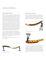
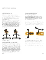
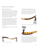
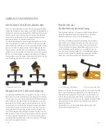
  Angle of the shoulder leg

6


 Angle of the chest leg

Adjusting the legs

Each leg has a Torx screw connecting the hinge joint with 
the base joint and a Torx flange screw connecting the base 
joint with the wooden bridge. When the Torx screws are 
tightened correctly the locking rings prevent movement 
between the hinge joint and the base joint and between 
the base joint and the wood. These four locking rings 
are essential to the functioning of the rest and should be 
replaced if lost or damaged (

6

 replacements included).

Adjustments to the legs should be made in small increments. 
For the maximum stability of the rest it is very important 
that the shoulder leg and chest leg meet the instrument at  
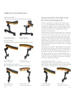
a straight angle when attached. When not attached the  
two hinge joints of the rest lean slightly towards each other 
(see picture 

4

). In order for them to do so and to ensure  

the ideal position of the wooden bridge in relation to the 
instrument, whatever adjustment is made needs to be 
divided between the shoulder leg and the chest leg.

After changing their position, look at both legs sideways 
and make sure the adjustment screws of the rubber feet 
are parallel to each other (see picture 

7

). When placed feet 

downwards on a flat surface, all 

4

 tips of the rubber feet 

should touch the surface. If they do not, adjust the tilt of 
the hinge joint of the chest leg. 

After making adjustments always check all screws have 
been tightened.

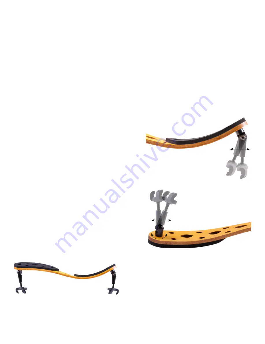
Narrowing the rest

Increasing the angle of the hinge joint of the shoulder leg 
inwards (see picture 

5

) will narrow the rest and create a 

stronger clamping action. In order to adjust the hinge joint,  
loosen the Torx screw enough to allow the joint to move. 
Move it to the desired position and tighten the Torx screw.

A similar adjustment needs to be made to the chest leg 
(see picture 

6

). To make the rest narrower, loosen the Torx 

flange screw and slightly rotate the base joint clockwise. 
After tightening the Torx flange screw, loosen the hinge 
joint. Hold the rest down on a table with the feet parallel  
to each other and all four hooks of the rubber feet touching 
the surface. Fix the resulting angle by tightening the Torx 
screw.

INSTRUCTION MANUAL

10

  EN

EN 

11

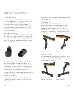
4

  Ideal angles of the legs 

Summary of Contents for KorfkerRest Model 2

Page 1: ...The ultimate in sound and comfort Model 2 Violin and Viola ...

Page 2: ...ENGLISH Quick start guide Instruction manual Page Handmade in Germany DEUTSCH Kurzanleitung Gebrauchsanweisung Seite 21 37 The ultimate in sound and comfort Model 2 Violin and Viola ...

Page 3: ...Key Quick start guide Instruction manual BENDING THE REST ADJUSTING THE LEGS Narrowing the rest Widening the rest Adjusting the tilt of the rest Returning the rest to its original position THE ERGOPACK 14 The most popular configurations for violin Adjusting the viola model to the size of your instrument REPLACING THE RUBBER PADS TUTORIAL VIDEOS CONTENTS PIRASTRO KorfkerRest for Violin Art No 70001...

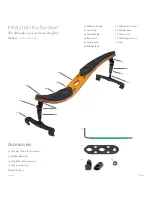
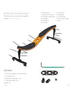
Page 4: ...ErgoPack with screws x Locking rings x Protection bag Wooden bridge Chest leg Shoulder leg Base joint Hinge joint Rubber foot Adjustment screw Rubber pad Torx screw Torx flange screw Eye 06 EN EN 07 The ultimate in sound and comfort Model 2 Violin and Viola ...

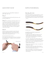
Page 5: ...sted Please refer to the section entitled Adjusting the legs on page 10 Ideally after bending it to the required shape give the wood 2 3 hours off the instrument to stabilize before regular playing QUICK START GUIDE INSTRUCTION MANUAL Step 1 Using the Torx key provided check that all the Torx screws are tightened before use Step 2 For viola players only Violinists follow step 3 Check the size of yo...

Page 6: ...houlder leg and the chest leg After changing their position look at both legs sideways and make sure the adjustment screws of the rubber feet are parallel to each other see picture 7 When placed feet downwards on a flat surface all 4 tips of the rubber feet should touch the surface If they do not adjust the tilt of the hinge joint of the chest leg After making adjustments always check all screws h...

Page 7: ...A small rotation will have a noticeable effect After tightening the Torx flange screw loosen the hinge joint of the chest leg Hold the rest down on a table with the feet parallel to each other and all four hooks of the rubber feet touching the surface Fix the re sulting angle by tightening the Torx screw Returning the rest to its original position In its original position and when not attached to t...

Page 8: ...lins see page 15 Many players have found that bringing the rest closer to the body has given them more freedom of movement of the left arm To try this use the adjustments for positions Closer to the Player see page 16 The standard options for installation of each ErgoPack joint have been given lettered pictures for ease of understanding see the following pages 14 EN HIGHER POSITIONS To elevate the...

Page 9: ...is still as desired and the positions of the legs are correct as described in Adjusting the legs Always tighten all screws well before using the rest The part of the ErgoPack not used for size adjustment can be used to create alternative positions as described in the ErgoPack section for violin see page 15 16 FURTHER OVER THE SHOULDER Position the rest further over the shoulder with both S1 and C4...

Page 10: ... 24 5 cm Do not need any of the ErgoPack parts for size adjustment In this case the ErgoPack may be used to create the same configurations as for the violin model as described in the ErgoPack section for violin see page 15 16 LARGE VIOLAS 24 5 cm and wider 24 5 25 5 cm Use S3 or C4 Using C4 the rest will point further over the shoulder using S3 the rest will lie more towards the chest 25 5 cm or w...

Page 11: ...DEUTSCH Kurzanleitung Gebrauchsanweisung Seite 21 37 The ultimate in sound and comfort Handmade in Germany Model 2 Violine und Viola ...

Page 12: ... Violin sowie für das Violamodel INHALT Ansicht Kurzanleitung Gebrauchsanweisung BIEGEN DER STÜTZE EINSTELLEN DER BEINE Verringern des Beinabstandes Verbreitern des Beinabstandes Anpassen der Stützenneigung Rückkehr zur Auslieferungseinstellung DAS ERGOPACK Standardmontagen des ErgoPacks für Violine Anpassung der Violastütze auf Ihre Instrumentengröße AUSTAUSCH DER GUMMIPADS ANLEITUNGSVIDEOS PIRAS...

Page 13: ...mit Schrauben Stk Sicherungsscheiben Stk Schutztasche The ultimate in sound and comfort DE 25 Schulterstütze Gelenkbein Brustseite Gelenkbein Schulterseite Gelenkbasis Gelenkkonus Gummifuß Stellschraube Gummipads Torx Schraube Torx Flanschschraube Auge Model 2 Violine und Viola ...

Page 14: ...inweise hierzu finden Sie im folgenden Abschnitt Einstellen der Beine Seite 28 Geben Sie dem Holz nach dem Biegen 2 3 Stunden Zeit um seine volle Belastungsfähigkeit wieder zu erlangen DE 27 GEBRAUCHSANWEISUNG 1 Biegen der Stütze Schritt 1 Vor dem Gebrauch kontrollieren Sie mit dem mitgeliefer ten Torx Schlüssel ob alle Torx Schrauben festgezogen sind Schritt 2 Nur für Bratschisten Messen Sie die ...

Page 15: ...che stehen sollten alle vier Hakenenden diese berühren Falls nicht verän dern Sie die Neigung des Gelenkkonus auf der Brustseite entsprechend Stellen Sie nach jederVeränderung sicher dass alle Schrauben festgezogen sind DE 29 Verringern des Beinabstandes Um den Beinabstand zu verringern und damit die Klemm kraft der Schulterstütze zu erhöhen lösen Sie die Torx Schraube des schulterseitigen Gelenks...

Page 16: ... Torx Flansch schraube wieder festgezogen haben lösen Sie jetzt die Torx Schraube des brustseitigen Gelenks Stellen Sie nun die Stütze mit ihren Füßen auf eine gerade Fläche und rich ten diese parallel zueinander aus Fixieren Sie den daraus resultierenden Gelenkwinkel indem Sie die Torx Schraube des Gelenks wieder festziehen DE 31 Rückkehr zur Auslieferungseinstellung Für optimalen Halt am Instrum...

Page 17: ...en Fällen verwenden Sie die Einstellungen für Schmalere Geigen auf Seite 33 Um beim Spiel mehr Bewegungsfreiheit des linken Arms zu ermöglichen verweisen wir auf die Einstellungen Näher zum Körper auf Seite 34 Verschiedene Standardmontagen der ErgoPack Teile sind zur Veranschaulichung auf den folgenden Seiten abge bildet und beschrieben DE 33 10 Zylindrisches Gelenkteil 11 Flaches Gelenkteil HÖHER...

Page 18: ...r jeweiligen Gelenkbasis und dessen Gelenkkonus Achten Sie darauf in jede Gelenkverbindung je eine Sicherungs scheibe einzulegen und alle Schrauben festzuziehen Extra Schrauben und Sicherungsscheiben sind Teil des Zubehörs Bei Montage eines ErgoPack Teils am brustseitigen Gelenk drehen Sie die Gelenkbasis im oder gegen den Uhrzeigersinn entsprechend der gewählten Einstellung wie im jeweiligen Bild...

Page 19: ... Austausch der Gummipads Wenn ein Gummipad abgenutzt ist entfernen Sie dieses indem Sie es von einem der Enden beginnend von der Stütze abziehen Lösen Sie die Folie von einem der mit gelieferten Ersatzpads ab und richten Sie das runde Loch genau um die Torx Flanschschraube aus Dann positionie ren Sie das große Auge am spitzen Ende des Gummipads bündig zu dem entsprechenden Auge im Holz Vor der Ben...

Page 20: ...NOTES NOTIZEN ...

Page 21: ...Pirastro GmbH Senefelderstrasse 80 63069 Offenbach am Main Germany www pirastro com www KorfkerRest com ...

Reviews: