background image

Summary of Contents for VSX-406

Page 1: ...S and Canadian models The serial number for this equipment is located on the rear panel Please write this serial number on your enclosed warranty card and keep it in a secure area This is for your security WARNING To P E iENT FIRE OR SHOCK HAZARD DO NOT EXPOSE THl APPUANCE TO RAIN OR MOIS TURE I for Canadian model CAUTION TO PREVENT ELECTRIC SHOCK DO NOT USE THIS POLARIZED PLUG WITH AN EXTENSION C...

Page 2: ...replace your obsolete outlet Do not defeat the safety purp0se of the grounding l fpe plug POWER CORD PROTtCTION Power supply cords should be routed so that they are not likely 10 be walked on or pinched by items placetl upon or agaonst them paying par JCUlar a11entoon to cords at plugs convenoence1ecep1 ades aodthepointwhere they exit from lhe product OUTOOOR ANTENNA GROUNDING If an outside antenn...

Page 3: ... 14 TUNING INTO STATIONS 14 PRESET TUNING 15 RECEIVING FM SIMULCAST TV PROGRAMS 15 OPERATING THE AUDIONIDEO COMPONENTS 15 PLAYBACK 16 RECORDING WITH A CASSETIE DECK 16 VIDEO RECORDING 16 SURROUND EFFECT AND DOLBY 3CH LOGIC 17 REMOTE CONTROL OPERATION 18 TROUBLESHOOTING 22 SPECIFICATIONS 24 IACCESSORY ITEMS FM Antenna 0 AM Loop Antenna Remote control unit r r I I _ Dry cell battery siie AA IEC R6 x...

Page 4: ...It makes you clearly perceive the directions where music comes from Real flow of sound also can be re created naturally using this feature You can feel as if being in the outstanding and expansive sound field When using DOLBY PRO LOGIC SURROUND a delay time setting of 20 ms is commonly used Use a different setting if you prefer Even if they do not bear the QOfooi av suRRouNDI mark some video recor...

Page 5: ... not be futly achieved NOTE To avoid interference with the picture on a nearby TVset use magnetically shielded speaker systems This is particularly important for the center speaker since it is usually located closest to the TV Position the left and right channel speakers at equal distanc es from the TVsetand approximately 1 8 m 6 feet from each other Position the center speaker above below or behi...

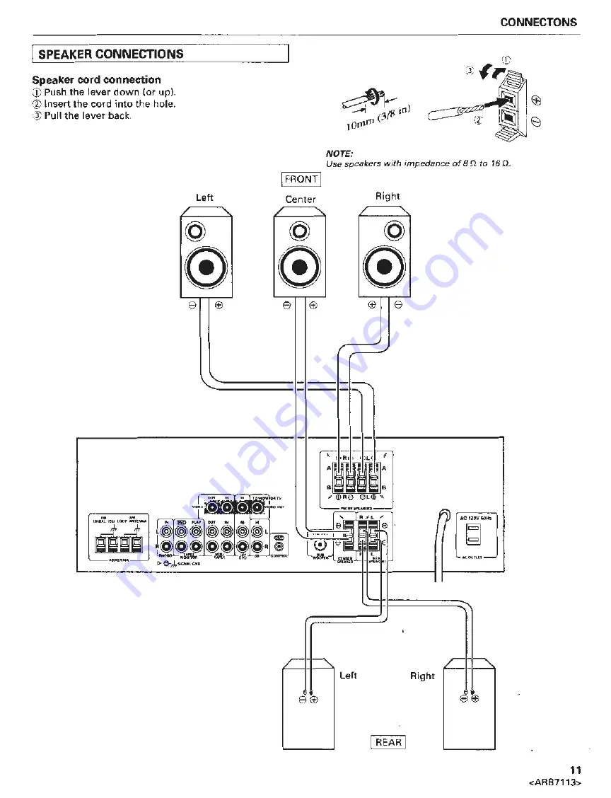
Page 6: ...rom the terminals or touch any other conductors Malfunctions or break downs may occur when conductors come into contact with each other Use front speakers with an impedance of 8 n to 16 n PHONO input jacks Connect to the output cables from a turntable X SIGNAL GND terminal Connect the turntable ground lead to this terminal 6 ARB71 13 Connect to audio components such as a second cassette deck or a ...

Page 7: ...on and off by the receiver s POWER switch Electrical power con sumption of connected equipment should not exceed 100 W 0 8 A NOTES This unit should be disconnected by removing the power plug from the wall socket when not in regular use e g when on vacation Do not connect appliances with high power consumption such as heaters irons or television sets to this AC OUTLET in order to avoid overheating ...

Page 8: ...l water pipe or grounding bar or wind it around a copper plate and bury it NOTE Never connect a wire to a gas pipe for grounding since sparks may ignite the gas IEXTERNAL AM ANTENNA If it is not possible to obtain adequate AM reception even by changing the orientation of the AM loop antenna a separate indoor antenna or an outdoor antenna should be installed INDOOR AM ANTENNA Use a vinyl insulated ...

Page 9: ...es generating radio frequencies Accessory FM antenna 25 Accessory AM Loop antenna Cassette deck 1 Turntable Cassette deck 2 CONNECTIONS Use if you want an additional power amplifier to boost center channel power output AM loop antenna and FM antenna connection Push the lever Insert the wire into the hole _ Pull the lever back CD player AC 120V60Hz AC wall socket To ooonect th p oneer S W1000 Powe ...

Page 10: ...CONNECTIONS IVIDEO SYSTEM CONNECTIONS 10 ARB7113 VCR IREC1 IPlAY IN OUT VIDEO TV monitor nn aUDa t R6 6L LD player or DVD player AC 120V601i ourur AC wall socket ...

Page 11: ...connection j Push the lever down or up Insert the cord into the hole Pull the lever back IFRONT I Left Center e e j11 10fl l NOTE Use speakers with impedance of8 n to 16n Right e 1 1 fM AM no AiCOUl l lf 1 1 1 1 L Left Right I e IREAR I 11 ARB7113 ...

Page 12: ... second cassettedeckand when monitoring recording a 5656 00 MASTER VOLUME control Use it to simultaneously adjust the sound volume from the front center and rear speakers Cf PHONES jack Connect the plug on your headphones to this jack Set SPEAKERS A and B switches to OFF if you want to cut the sound from the speakers and listen to it only through the headphones SPEAKERS buttons A Bl ON OFF switche...

Page 13: ...N _li_c S BASS SFC PRO LOGIC FRONT PANEL FACILITIES STATION button Use to call preset station numbers in ascending order Use to call preset station numbers in descending order BASS control Use to adjust the low frequency level Turn clockwise to boost bass and counterclockwise to attenuate bass TREBLE control Use to adjust the high frequency level Turn clockwise to boost treble and counterclockwise...

Page 14: ...ceived when the MONO indicator is out the STEREO indicator lights and sound is in stereo If an FM stereo broadcast is received when the MONO indicator is lit the sound will be monaural If there is interference during STEREO mode recep tion switch to MONO The sound will become monau ral but interference will be reduced 1 Use the FM AM button to select either FM or AM 2 Press the TUNING buttons unti...

Page 15: ...r with the class button 2 Press the STATION buttons to select a station 3 Adjust the volume and tone controls as desired NOTE Even if the receiver power cord is unplugged data remains in memory for several days If the contents of the memory are erased preset once more Last station memory When t he POWER switch is pressed to turn the power on the last station received before the power was previousl...

Page 16: ...recording from a LaserDisc to VCR LO DVD 2 Begin recording on the VCR For VCR select a line input external input 16 ARB7113 If you select a music source other than TAPE 2 switch OFF the TAPE 2 MONITOR 2 Operate the appropriate audio video component to playback the program source For a video source switch the TV connected to this unit to the video input mode 3 Adjust the volume and tone controls as...

Page 17: ... the following order Front Left Center L_ Surround Rear Front Right 7 Adjust so that the volume level Is the same from each of the speakers Use the CENTER LEVEL buttons of the remote control unitto adjustthe centerspeaker volume level 2 Use the REAR LEVEL buttons of the remote control unit to adjust the rear speaker volume level 3 8 Press the remote control s TEST TONE button to switch the test to...

Page 18: ... receiver The remote control unit may be used w ithin a range of about 7 meters 23 feet from the remote sensor within angles of up to about 30 degrees Performance of the remote control unit is adversely affected in the presence of a strong fluorescent light Keep such lights away especially from the sensor win dow Battery Replacement As battery power runs down the range over which the remote contro...

Page 19: ... OFF MUTING OFF SFC MODE OFF FUNCTION TUNER SUPER BASS OFF FM And SPEAKERS buttons switch as follows NOTE Press the RETURN button and the last FM station selected is received If reception of the frequency last selected is not possible the mode automatically switches to AUTO TUNING CENTER MODE AUDIONIDEO switch YIDEO position Functions as a CENTER MOOE button enabling selection of the DOLBY PRO LOG...

Page 20: ...button A simple way to store your favorite tracks in memory for future playback is to press the BEST button during play back of the tracks Up to 25 tracks can be stored in the best memory 20 ARB71 13 DISC SELECT I buttons Use to select a disc with a file type CD player Only the button may be used to select the DISC No 1 to 6 for a multi CD player or used to select DISC I II for a twin tray CD play...

Page 21: ...ast forward DISC SIDE iA 8 button Changes the disc side in an LD player capable of playing both sides of a disc LO POWER button Switches LO player power ON OFF REMOTE CONTROL OPERATION TV OPERATION Set the AUDIONIDEO switch to VIDEO Operation buttons TV VOL VOLUME buttons Raises and tow ers the volume TV CH Channel buttons Switches TV channels in order TV POWER button Switches the power of the TV ...

Page 22: ... Station has not been tuned in to correct frequency Antenna has not been connected or has become disconnected FM reception Accessory FM antenna remains bun died up or it is not pointing in right direction Weak broadcasting station signals AM reception AM loop antenna is not pointing in right direction Weak broadcasting station signals Noise being picked up from this unit and other equipment especi...

Page 23: ...estore normal operation turn the power off and then on again or unplug the AC power cord and then plug it in again MAINTENANCE OF EXTERNAL SURFACES Use a polishing cloth or dry cloth to w ipe off dust and dirt When the surfaces are very dirty wipe with a soft cloth dipped in some neutral cleanser diluted five or six times with water and wrung out well and then wipe again with a dry cloth Do not us...

Page 24: ...er 24 ARB7113 VIDEO Section Input Sensitivity Impedance VCR LD 1 Vp p 75 n Output Level Impedance VCR 1 Vp p 75 Q Frequency Response VCR LO MONITOR 5 Hz to 7 MHz g dB Signal to Noise Ratio 55 dB Cross Talk 55 dB FM Tuner Section Frequency Range 87 5 MHz to 108 MHz Usable Sensitivity Mono 11 2 dBf IHF 1 0 µV 75 Q 50 dB Quieting Sensitivity Mono 16 8 dBf Stereo 38 6 dBf Signal to Noise Ratio Mono 73...

Page 25: ...his manufacturer and the Electronic Industries Association s Consumer Electronics Group recommend you avoid prolonged exposure to excessive noise This list of sound levels is included for your protection Decibel Level Example 30 Quiet library soft whispers 40 Living room refrigerator bedroom away from traffic 50 Light traffic normal conversation quiet office 60 Air conditioner at 20 feet sewing ma...

Reviews: